More information about this website & why it was created can be found by visiting this website's 'front' pages (link opens in a new window).
This page primarily focuses on types of railway electrification, the benefits of electrification within the context
of the railway sphere of operations and the present-day scene here in Britain
| Whilst many of the comments on this page will also apply to all the different types of transport looked at on this website to avoid too much duplication this page does not cover the environsensible etc., benefits of electric traction per se as those issues are fully explored on the Electric Buses page (link here). |
Navigating through this website is easier with the navigator frame which should be to the left of this window.
If it is not there then click here to turn it on!
Alternatively there is a system map at the foot of this page.
More information about this website & why it was created can be found by visiting this website's 'front' pages (link opens in a new window). ![]()
 |
 |
||||||||||||||
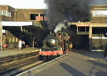
Just in case anyone needs reminding - steam engines may be glamorous, but look at that black smoke - an environmental disaster on wheels! In country areas burning embers from coal fuelled steam engines often cause lineside fires.
 The above image is a
video-still - click the image or the projector icon to watch a short film on the ‘YouTube’ film / video website showing the train as it passes through the station. The above image is a
video-still - click the image or the projector icon to watch a short film on the ‘YouTube’ film / video website showing the train as it passes through the station. |
Diesel trains are less dirty than steam trains but they too face environmental challenges which at this almost fully enclosed station (London Waterloo) resulted in the installation of a waste air extraction system so that the passengers and station staff do not have to breathe the carcinogenic diesel engine exhaust fumes. | ||||||||||||||
|
Electric railways have the potential to be the least environmentally damaging form of traction. Although this depends on how the power is sourced, even the dirtiest emissions are easier to reduce at a few power stations compared to many hundreds of moving trains. Electrification is also a more efficient way of transmitting power, especially on the busiest and most heavily trafficked routes where any additional capacity (either through longer trains or more frequent services) will require proportionally less additional energy when it comes from a common source rather than from fossil fuel traction units on each train. Electric locomotives can deliver as much as 2½ times the tractive power output of an equivalent diesel. With electric traction it is also possible to further increase efficiency through regenerative braking, which means that a slowing-down train can use its electric motors as generators and either recycle energy back into the system for other electric trains to use or recycle the energy to onboard storage for it to use when next accelerating. Electric traction offers significantly improved performance when ascending gradients, plus the possibility of using regenerative braking to cost efficiently maintain safety whilst descending. For passengers the advantages of electric traction includes improved overall performance and less vibration which results in faster, more comfortable, smoother and quieter journeys. The improved acceleration also means that extra stations can be served with less time penalty - this is especially beneficial to users of minor stations which might otherwise have a less frequent service. Experience has shown that the very act of investing in railway electrification also gives passengers greater confidence that the line is valued by the railway operators and therefore has a secure future. The sparks effect is a well proven phenomena whereby passenger numbers significantly increases when a line is electrified. Transport operators usually find that thanks to the fewer moving parts and the 'slide out / slot in' modularity of the traction packages electric trains are simpler and cheaper to maintain. As with trolleybuses the reduced vibration and sheer ruggedness of the electric traction system means that although they are more expensive to initially purchase their operational lives will be far longer than their fossil fuel counterparts, so in the longer term they will be more cost efficient. Critics of electric traction often allege that when the necessary electricity is sourced from fossil fuels all that is really happening is that the pollution is being shifted up the energy chain to the power station. However, following extensive research in the University of California it has been found that even with low grade coal that produces a lot of carbon dioxide (as is used in Germany) electric traction offers an almost complete elimination of carbon monoxide and hydrocarbons, resulting in a significant global air quality benefit. Of course if the fuel used is high grade coal or natural gas (or another so called 'cleaner' fossil fuel) the benefits are even admirable. Experience in Sweden has shown that when a type of coal-burning power station known as 'pressurised fluidised-bed' is used then the emission of sulphur oxides and nitrogen oxides are also considerably reduced; furthermore, when these facilities are linked in with combined heat and power facilities (ie: provides both electricity and hot water which can be made available to industrial and domestic consumers alike) then they are about 40% more efficient than their traditional large coal burning equivalents, (75% efficient opposed to 35% efficient) and are so clean that they can even be located within cities. Of course where the electricity is sourced from renewable sources (eg: hydro, wind, waves, solar, geothermal and tides) it will be 100% non-polluting, it is to be very much regretted that despite the potential benefits (and the globally recognised need for humankind to adopt more environmentally sound policies - anyone remember Rio 1992??) only the first two of these are used to any extent. People who live near rail lines have found that electric trains are also quieter than diesel trains (both locomotives and multiple-unit passenger carriages) and therefore are better neighbours. |
|||||||||||||||
 |
 |
||||||||||||||
| Britain's first electric railway was the Volk's Electric Railway which opened on 3rd August 1883. It runs along the sea front at the fashionable south coast seaside resort of Brighton and was named after Magnus
Volk who was an Electrical Engineer to Brighton Corporation. As this picture suggests, the line is still open. Originally it was electrified at 50V DC but in 1884 this was increased to 160V DC with one of the running rails
also acting as the live and the other as the return. However after severe problems with electricity leakage an insulated 3rd rail located offset between the running rails was installed for the live, with return now being
via both running rails. Nowadays it is powered at 110V DC. This view was taken at Black Rock station, which is the eastern terminus. |
The first overhead wire powered electric railway 'anywhere' planetwide opened in 1893 on the Isle of Man. Featuring tramway-style red painted trolley poles collecting 500V DC from the overhead wire the Manx Electric Railway still uses its orginal trains. Also on the Isle of Man but not shown on this page is the Snaefell Mountain Railway which uses a slightly higher voltage of 550V DC. |
||||||||||||||
Railway Electrification TypesRailway electrification will usually take one of two forms - via wires suspended over the tracks or by way of one (or two) extra electrified rail(s) located alongside the running rails (ie: the rails used by the trains' wheels). The overhead (catenary) wire system is more usual for long distance lines whilst the electric (conductor) rail(s) system (which is usually referred to as 3rd [or 4th] rail) is more often used on city-specific urban rail systems (sometimes called metro / subway / rapid transit). But, as ever, there are exceptions. Trains which are powered using the overhead wire system will usually collect their power via roof-mounted pantographs. A photograph of a pantograph is seen further down this page. Information on how pantographs work and some different types of overhead wiring can be found at this link:
Because of the physical presence of the overhead wires the overhead wire system is sometimes thought to be somewhat unsightly - although modern installations can be less visually intrusive than older historic systems - but by keeping the high voltage well away from track level this system is considerably safer in areas where people might have access to the tracks. Trees near to railways which are electrified using overhead wires need to be pruned to ensure that branches do not contact and possibly become entangled with the wires. The overhead wires are sometimes affected by strong winds and freezing rain which can bring the wires down, stopping all trains. Another cause of grief which can cause trains to be stopped comes from plastic sheeting which is blown into the wiring and then becomes entangled with the train's pantograph. Since the train is usually moving when this happens it is not unusual for the wiring to become entangled around the pantograph with the damage extending the entire distance from point of impact to where the train came to rest. Typical* overhead wiring voltages used nowadays include 750V DC (primarily on light rail systems) 1,500V DC, 3,000V DC, 15,000V 16 2/3Hz AC and 25,000V 50Hz AC (or 60Hz depending on the frequency of the local mains electricity system). Some countries which use the 15kV 16 2/3Hz AC system have changed the terminology to 15kV 16.7Hz AC, however since the power in the overhead wires is always fluctuating* (as detailed below) so in reality the power supply remains exactly as it was before. There are also a few VHV (very high voltage) heavy freight (mining) railways located in sparsely populated isolated areas in North America and South Africa which are energised at 50kV (50,000V) 50Hz (or 60Hz) AC. Virtually always when alternating current is used it is single-phase, however in the early part of the 20th century some routes were electrified using a three-phase AC system which requires the trains to collect power from several overhead wires. Italy had the most three-phase AC routes, including some main lines. Three-phase AC is especially suited to railways in mountainous areas (such as are found in parts of Italy) where downhill trains are frequently able to use regenerative braking to power trains travelling uphill. The disadvantages of this system include that the trains are restricted to just a few set speeds which (in those days) required complex arrangements within the locomotives to change, and the need for two or three overhead wires (one per phase) with an absolute requirement that they never come in contact with each other. This made for especially complicated wiring at junctions where routes join / diverge. Systems which only use two overhead wires use a rail for the third phase. As technology has improved virtually all three-phase routes have been converted to single phase, with just four three-phase mountain railways still remaining. Because of their low speeds these railways are able to use simpler and cheaper overhead wire power technologies such as are used by some light rail systems. However since AC motors tend to be of a simpler design and have lower & cheaper maintenance requirements compared to DC motors so many trains nowadays use multiphase AC motors, with solid-state electronics converting whatever power is supplied via overhead wires / third rail / onboard diesel generator to multi-phase AC power. The four railways which still use the three-phase AC system also all use twin overhead wires and are: the Gornergratbahn and the Jungfraubahn in Switzerland, the French Petit train de la Rhune and the Trem do Corcovado (Corcovado Train) in Rio de Janeiro, Brazil. |
|||||||||||||||
The opening of the Croydon Tramlink system was slightly delayed because of a return current leakage to earth near to the tramstop which serves the mainline railways' East Croydon station. Being a new system this issue
had to be resolved before the system could open as otherwise if electrolysis had resulted in damage to underground utilities the various utility companies would have been seeking (possibly very expensive) redress from the tramway operators. |

Croydon trams (in their original livery) at the 3 track tram station right outside the main (East) Croydon mainline railway station. |
||||||||||||||
|
The electrified conductor rail(s) system is cheaper and easier to install but can pose a safety hazard to people who trespass over the railway as well as track maintenance workers and sometimes animals too (especially small mammals). The 3rd rail variant features one extra rail which is usually used by the live / positive current with the electrical return being via the running rails. The 4th rail system uses two extra rails with there being one each for the live and return. In this way there is a closed circuit from where the electricity is less likely to leak into the surrounding ground - a process which can cause electrolysis, corroding metal structures - such as water pipes, sewers, and whatever else is in the ground - to such an extent that they need (possibly expensive) replacement. Typically* the electric rail systems will use voltages between 600V DC and 1.5kV (1,500V) DC - higher voltages can become impractical because the electricity would arc from the rail - literally jumping or short circuiting to the ground - and completing the circuit back to the power station without providing any useful benefit. Lower voltages require the electrical feeder or sub-stations to be installed at more frequent intervals along the line in order to feed electricity into the system, increasing the cost of operating the railway. Electric rail systems always use DC electrics. There are several variants to 3rd rail power supply systems with power being collected from the 'top', 'side' or 'bottom' of the rail. Side and bottom contact are safer as the simple expedient of a cover over the top of the rail affords a level of protection against a person accidentally stepping onto the rail. The covers also help protect against snow and falling leaves - with the top contact system it is too easy for snow and ice to encrust the top surface of the conductor rails in a way which compromises the ability of the train to collect electrical power. Occasionally this can cause trains to become stranded, more often however there is just a lot of noise and spectacular sparking as the high currents burn through the moisture. If this sparking happens whilst a train is stationary (ie: stopped at a red signal or calling at a station) it can result in the 'shoe' that collects the power from the conductor rail welding itself to the electric rail!! Although rare, this has happened on open-air sections of London's Underground - causing delays whilst a welder is summoned to free the train. This might sound surprising but it can - and sometimes does - happen that a train becomes stalled due to loss of contact with the electrified rail. This mostly happens to single-unit multiple-unit trains and electric locomotives, and would be caused by them travelling slowly over complicated junctions where the gaps in the conductor rails are so long that none of the train's power collection shoes are above (and therefore in contact with) the conductor rails. It is less common when a train / locomotive is travelling at even a modest speed - because usually there will be enough inertia for it to reach the next conductor rail before stalling. It is also less common for this to happen to trains formed of two or more multiple-units - because usually even if one of the units finds itself without power the other unit(s) will still have power and this will be enough to keep the entire train moving. Apart from steel wheel railways conductor rail power supply systems are used on the urban metros and monorail systems which use rubber tyred trains. |
|||||||||||||||
 |
 |
||||||||||||||
Virtually the entire Swiss railway system is now electrified, mostly at 15kV AC using overhead wires although some routes use lower voltages and two still use the three-phase AC system which requires the trains to
collect power from several overhead wires. The Jungfraubahn, as seen here, opened in 1912 and is 9km long. It is electrified at 1125V AC 50Hz.
Some urban transport systems use a fixed rail as an alternative to overhead wires. This is especially advantageous in tunnelled systems where space above the train is very limited, and the upward 'movement' associated with traditional flexible overhead wire systems (when the pantograph, which by its very nature must exert an upward pressure, passes underneath) could make overhead electrification impracticable. |
|||||||||||||||
 |
 |
||||||||||||||
| Overhead fixed rail power conductor on the Barcelona, Spain, Metro, which converted from third rail to overhead power supply
for reasons of safety and economy (cheaper track maintenance).
Image courtesy of the Association for the Promotion of Public Transport http://www.laptp.org/. |
An issue often faced by top contact electric rail systems is that in wintry weather snow and ice on the conductor rail can interfere with power collection by the pick-up shoes. The reduced contact usually leads to severe arcing as seen in this still image taken from video. If the snow or ice are thick enough it can even result in a total loss of power transfer with the train then becoming stranded. | ||||||||||||||
 |
 |
||||||||||||||
| Apart from London's Underground the only steel wheel urban railway which uses a 4th rail system is Milan, Italy, metro line M1.
Here the outer conductor rail comprises a lateral flat bar with power collected via side contact whilst the electrical return is via a more conventional top contact conductor rail located centrally between the running rails. For safety reasons line M1 trains use pantographs (with return current passing through the running rails) whilst in the depot. The line is electrified at 750V DC. In addition, part of the route of line M1 is also equipped with an overhead power supply so that 1.5kV DC trains from lines M2 and M3 can access a depot located on line M1. |
Third rail electric railway at Chamonix, France. In common with many overseas railways this line is partially unfenced - something which, on this visit in 1980, nearly cost me my life when I explored a siding that had rusty looking rails and believing it to be part of a closed railway nearly stepped on to the 3rd rail as I crossed the tracks. Only later (when I saw trains in motion) did I discover that the line was still open and the electric rail 'live'. The line is electrified at 800V DC. |
||||||||||||||
*Note that the typical voltages detailed above are just that - ie: only typical voltages. Actual voltages can vary somewhat, for example on 750V DC routes the actual voltages can vary between 500V and 900V (or even 1000V as a 'peak' voltage) whilst on 25kV AC routes the permanent voltages can vary between 19kV and 27.5kV, with peaks as low as 17.5kV and as high as 29kV (17,500V and 29,000V). Emerging technologies are also seeing the development of some new forms of power supply systems, such as the use of induction. However since these tend to only involve light rail and tram systems so they are looked at on the Trams, Streetcars and Light Rail Vehicles page. Combination SystemsSome systems use third rail for part of the route, and overhead wires for the remainder. These exist sometimes because of the connection of separately-owned railways using the different systems, or because of local regulations. In New York City some electric trains use third rail to reach Grand Central Terminal on the former New York Central Railroad (now Metro-North Railroad) and use overhead wires when they travel along the former New York, New Haven and Hartford Railroad (now Amtrak) route to Connecticut. The changeover is made 'on the fly' (ie; whilst moving). The Blue Line of Boston's MBTA uses third rail electrification on the city centre subterranean part of the line and overhead wires whilst above ground. The changeover is made whilst calling at the station which serves the airport (named 'Airport'). Converted from a former narrow-gauge steam railway (which was electrified prior to being rebuilt as a subway line) the choice of overhead wires for the surface section of line was made to lower the risk of accidental electrocutions whilst passing through some densely populated areas. In Oslo, Norway, the T-bane system (urban / underground railway) includes both older urban light railway routes which were built with overhead wires and newer routes that right from the outset used the third rail system. In spring 2010 the last section of line was closed for for conversion to third rail, this was the Holmenkoll Line which reopened in December of the same year in its new format. Whilst most of the S-Bahn system in Hamburg, Germany is electrified at 1.2kV DC third rail, a 32km extension of line S3 which was opened in the winter 2007 / 8 timetable has overhead wires which are electrified at 15kV AC 16.7Hz, and the trains which were needed for this service were adapted so that they could be powered on both power supply systems. As an aside, when the Hamburg S-Bahn first opened in 1908 it was electrified using overhead wires at 6.3kV (6,300V) AC 25 Hz, but when in the 1930's the equipment was becoming life expired it was decided that since the third rail electrification in Berlin was working very well so a similar system should be installed in Hamburg as well. The only difference was that Hamburg would be given a higher voltage as this would improve the trains' acceleration. The first third rail trains started running in 1939, but because of the war the conversion from overhead wire to third rail was only completed in 1955. More detailed information on railway electrification systems plus a reasonably full list of the different voltages used - and where - can be found on these two pages of the online 'Wikipedia' encyclopædia:
This page also explains more - the thumbnail images can be clicked to see larger versions.
Electric Trains in the British IslesNowadays most mainline overhead electrification in mainland Britain is at 25kV AC 50 Hz. In the past some routes used other voltages (primarily but not exclusively 1.5kV DC and 6.25kV [ie: 6,250V] AC 25 Hz) but - with one exception - they have either been converted to the standard (eg: Manchester to Hadfield / Glossop) or the lines closed (eg: Lancaster to Morecambe / Heysham). Over the course of time some lines have been converted between different voltages several times. Light rail systems tend to use lower voltages (typically 600V DC on older systems & 750V DC on newer systems) as this is safer where on-street operation is involved. In Britain we also used to have many electrically operated industrial railways which were located at places such as at coal mines but they have now all been closed. The 'Southern' 3rd rail system mostly uses (a nominal) 750V DC, except on lines which at one time were shared with Eurostar trains where the voltage was increased to 850V DC. At first the London Brighton and South Coast Railway electrified its suburban services at 6.7kV (6,700V) AC 25 Hz using the overhead wire system but after grouping in 1923 the Southern Railway decided to standardise on the London and South Western Railway's (LSWR) (then) 650V DC 3rd rail system which was also in use elsewhere in south London. It is said that this choice was partly influenced by a greater route mileage having already been electrified using the 3rd rail system. For a while some railway depôts in Southern England were electrified at 750V DC via overhead wires instead of 3rd rails as a safety measure for railway staff. Another constituent of the former Southern Railway - the South Eastern and Chatham Railway - was planning to use a 4th rail system energised at 1.5kV but railway grouping occured before this was installed. The trains seen in the two views below are known as Class 313 Electric Multiple Units. These were the first British electric trains which could use both the 25kV AC overhead wire and the 750V DC 3rd rail systems |
|||||||||||||||
 |
 |
||||||||||||||
| Overhead wire power comes via a pantograph which is (usually) located on the train roof. Powerful springs (or compressed air) exert an upwards pressure forcing the pantograph up to the wires, which are kept under tension to resist that upwards force. | Top contact third (and fourth) rail systems use heavy 'shoes' which are suspended from the bogies (wheel units) to collect power by sliding over the top surface of the electric conductor rails. | ||||||||||||||
| A short
film showing some Class 313 trains switching between overhead wire and 3rd rail modes has been placed on the ‘YouTube’ film / video website. This can be watched by clicking either the projector icon or this link
http://www.youtube.com/watch?v=TPg0sZPl28s London's Underground uses the 4th rail system whereby the electrical return uses a conductor rail located centrally between the running rails. This is supposed to reduce the chance of stray currents damaging tunnel walls, nearby utilities, etc. Although the underground network is mostly nominally electrified at 630V DC the system actually works so that +420V DC is collected from the outer 'positive' (3rd) rail and -210V DC from the centre 'negative' (4th) rail. Where underground trains operate over electrified mainline railway tracks they collect the full line voltage from the 3rd rail and the 4th rail is electrically bonded to the running rails - which also act as return for the mainline trains. At the boundaries where the trains pass between sections of line electrified on the two systems there are gaps in the electrified 3rd and 4th rails which are of sufficient length to ensure that the trains do not (even briefly) electrically connect the systems together. The mainline railway routes which are shared with underground trains are typically electrified at between 660V and 750V, although when the voltage fluctuations described above are bourne in mind so trains using these routes have been known to receive as much as 900V DC. Since this is a known phenomena the trains which operate over the relevant routes are built to withstand this voltage. Apparently in 1930 the voltage was described as being '550V/600V', but during the 1930's it was raised to approximately 630V. In October 2016 the section of the Metropolitan line between Harrow-On-The-Hill and Amersham / Chesham / Watford became the first part of the London Underground network to have its line voltage raised from 630V to 750V, with the outer 'positive' (3rd) rail now being +500V DC and the centre 'negative' (4th) rail at -250V DC. Reasons for this power upgrade include that recently introduced new trains need more power to operate extra features (such as regenerative braking, full air-conditioning and high rates of acceleration) which were not found on the older trains. In the longer term it is planned to upgrade more (and eventually all) of the Subsurface network and possibly even the entire Underground system to the higher voltage. The reasons why this process will take many years include the amount of time and funds needed to modify the substations / power supply system and the incompatibility of the existing fleets of older trains with the higher voltage. Therefore some sections of the network will have to remain at the lower voltage until either the older trains are replaced or they are modified to make them compatible with the higher voltage. For the Subsurface network this includes the routes in west London where they share tracks with Piccadilly line trains - which date from 1973. For the record the Clapham Common - (King William Street) \ Moorgate - Euston section of what is now known as the Northern Line was originally electrified at 500V DC using an off-centre third rail set 15" (355mm) from the inside edge of the running rail on the east side of the tracks and about 3/4" (18mm) below them. The offset from the centre of the tracks was decided upon because it created space for the couplings between the carriages. This railway used an unusual three-wire DC system with the third rail being electrified at +500V in the northbound tunnel and at -500V in the southbound tunnel. This was because the initial system was fed directly from the dynamos in the surface power plant at the Stockwell end of the line and it was important to minimise the voltage drop as much as possible, especially because of the rather steep gradient on the approach to the northern terminus station. Concurrent with the 1923-4 closure for widening of the tunnels to make them suitable for standard sized London 'tube' trains the surviving section of line was also converted to standard 4th rail operation. In addition, from its opening in 1906 until the commencement of services to Watford Junction in 1917 the Bakerloo Line used a reversed power supply system whereby the centre rail was the 'positive' and the outer rail was used for the 'negative'. This was done to counter power supply problems caused by too much current leaking to earth via the cast iron tunnel segments. (NB: " means inches; metric conversions are approximate). Because of the high cost of maintenance London Underground did once state a desire to switch to an overhead power supply system and in the late 1990's it was believed that the Victoria Line would be converted first, concurrent with the introduction of a new fleet of trains. However this idea fell by the wayside when train operations were privatised. It would have been interesting to see how they would have converted the Piccadilly and Bakerloo lines which use the smaller profile 'tube' trains but also share tracks with full size trains. Although at one time the different British railway companies located the electrified rails at different distances from the running rails and different heights from the ground a 'standard' has come about using the LSWR / London Underground system whereby the positive conductor rail is outside of the running rails (can be either side, but not usually both sides at the same location) and offset 3" (8cm) higher plus 16" (41cm) sideways as measured from the inside of the nearest running rail. Where used the 4th rail is located centrally between the running rails and 1½" (4cm) above it. Nowadays only tracks served by London Underground trains need this extra rail. One of the few surviving exceptions to the standard is on the Central Line which when it first opened in 1900 used a centrally located positive 3rd rail (energised at 550V DC), and due to a restricted loading gauge when (in 1940) it was converted to standard it was found necessary to locate the outer rail an extra 1½" (4cm) higher than normal. This only applies to the earliest sections of the line, between Liverpool Street and White City, and as a result only trains fitted with 'high lift' shoegear can travel over this route. |
|||||||||||||||
 |
 |
||||||||||||||
| The London Underground uses a 4-rail system where the electrical return is isolated from the running rails (the rails used by the train's wheels). Sparks like this are quite normal and occurs when the electric power collection 'shoes' of a train that is motoring (ie: drawing power) reach the end of a section of electric power (conductor) rail. |
The Docklands Light Railway features a modified 3rd rail system where powerful springs force the 'shoe' upwards so that it collects power by sliding along the underside of the conductor rail. | ||||||||||||||
|
Apart from the Southern and Underground networks London also has several other 3rd rail systems:- |
|||||||||||||||
London's Finsbury Park - Highbury & Islington - Moorgate deep level tube line was built as a self-contained shuttle which used an incompatible 575V DC 4th rail system where the two conductor rails were 10" (25cm) outside and 2" (5cm) above the running rails, one each per side. One reason why this unusual arrangement was chosen is that mainline trains used chain link couplings that hung down between the running rails and it was likely that these would touch a centrally located conductor rail. This was changed to a standard 4th rail system when London Transport tube trains replaced the original trains in the late 1930's. More recently with its incorporation into the Great Northern Electrics suburban mainline railway electrification scheme in the 1970's the section between Drayton Park and Moorgate stations was converted to 3rd rail only and become part of British Railways, using the Class 313 twin-system trains seen here and elsewhere on this page. |
 Whilst travelling in third rail mode 313 026 in Network SouthEast livery calls at Highbury and Islington station |
||||||||||||||
|
Note that this line is no longer shown on the famous London UndergrounD map. This is because it is not operated as part of the London Underground or any other railway service owned by Transport for London Away from London four other cities use / did use electric rail systems; all bar one of these using the top contact system as on the Southern Electric:- For reasons of safety it is very unlikely that any new railway electrification schemes here in Britain would be allowed to use the top contact electric rail system - although extensions to the existing systems are allowed. Instead new schemes would be energised via bottom contact 3rd rail or (more likely) overhead wires. |
|||||||||||||||
 |
 |
||||||||||||||
| Away from London and Southern England the only other locality in Britain where there is a mainline railway service powered via electric rails is Merseyside (Liverpool). A southbound Merseyrail train for Hunts Cross leaves Sandhills station. |
The Glasgow Subway is a city-specific system operated by a local transport authority - it is not part of the former British Railways. When it opened in 1896 it became the only underground railway system 'anywhere' globally to feature cable haulage. Electrification came in 1935 using an outside conductor rail energised at 600V DC. | ||||||||||||||
 |
 |
||||||||||||||
| Former LNER 'Tyneside Electrics' 3rd rail electric train which dates from 1937 seen at Tynemouth station shortly before the line was de-electrified by BR in 1966. Image courtesy of Dr I Frew. NB The clickable large image has been sourced from S-VHS-C videotape and is a little fuzzy. |
Modern-era 'Tyneside Metro' train calling at the partially refurbished historic ornate Tynemouth station in 2001. Nowadays this is the only British railway system to be powered at 1.5kV DC. | ||||||||||||||
 |
 |
||||||||||||||
The Manchester - Bury (- Holcombe Brook) line was initially (partially) electrified at 3.5kV DC using overhead wires but in 1918 this was changed to the unique 1.2kV DC side-contact third rail system. The view on the left was captured just weeks before closure for conversion to the
Metrolink light rail system and the preparatory earthworks for its overhead wire supports can be seen on both sides of the tracks. The view on the right shows the same location a few years later, when Metrolink had become well established.
Information sources include:
Recent Railway Electrification & Attempts At Railway ElectrificationMissed Opportunity -- Yet Again!In 1981 British Rail and the Department of Transport produced a report (Review of Mainline Electrification) which concluded that even on purely commercial grounds not only was 'a substantial programme of railway electrification financially worthwhile' but that the more extensive and faster options would be better propositions than the more modest ones. It also suggested that the most cost effective way to electrify railways would be by a rolling programme whereby a specialised team of experts will electrify a whole series of lines sequentially (ie: when one line is completed they move to the next) as it would optimise resources and expertise, plus give industry the steady long term order book that creates economic stability. What this report suggested has often been dubbed the network effect - ie: the more lines electrified the more it would be financially advantageous to electrify even more lines! This is because it would enable more trains to run through services without needing a change of motive power en route, and help avoid (as has happened instead - see below) the wasteful situation arising whereby diesel trains travel significant distances over electrified railways because small sections of the journey involves using non-electrified lines. However despite the manifold potential benefits to British industry and the wider economy the government refused to allow the creation of such a long term investment plan to which it would have to keep, and instead retained what many people see as a myopic policy of judging every line in complete isolation. |
|||||||||||||||
 |
 |
||||||||||||||
Diesel trains running "under the wires" - an issue that affects both passenger and freight services.
Both the types of passenger train / freight engine seen here have been introduced since privatisation. Since Privatisation - Stagnation!In the mid 1990's the government split the railways up into a myriad of small 'bite sized' chunks which it then privatised. The company that now runs the railway infrastructure does not benefit from investing in railway electrification whilst the train operating companies have such short franchises that there is no benefit to them in making this kind of investment as they could spend the money and then loose the franchise - effectively losing the investment they made. In addition, with each TOC more or less solely interested in what is best for it and not the wider railway system / environment etc., so some of them have even been replacing electric trains (both locomotive-hauled and multiple-unit) with diesel multiple-unit trains. There have been several reasons for this, which include:
As a result the first two decades after railway privatisation saw there being virtually no new railway electrification (in England), except the occasional fill-in scheme to provide diversionary routes for existing electrified lines during upgrading works. The only electrification scheme which saw diesel trains being replaced by electrics was in Yorkshire, but this was actually a leftover that had been began by the former British Railways, and because of funding problems resulting from railway privatisation it opened with unreliable 30 year-old cast-off electric trains from London! Even so many passengers still preferred the older electric trains to the much newer diesel trains they replaced. Eventually though the route received a fleet of brand new Class 333 electric multiple units since then passenger numbers have been growing at up to 19% per year. Indeed since they began (in 1995) the electric services have been so successful that the trains now carry as much as 75% of some commuter flows (ie: just 25% of passengers from some areas now travel by road) and despite having been lengthened from three to four carriages at busy times severe overcrowding can be a problem, proving that when given an attractive & viable alternative choice to travelling by road people will choose to use it! In many ways this passenger growth is typical of what happens with railway electrification - even here in Britain previous railway electrification schemes have proven the sparks effect to be a phenomena which does boost passenger numbers. |
|||||||||||||||
 |
 |
||||||||||||||
| Seen near to Saltaire station this is one of the electric Class 333 trains which serves the West Yorkshire Airdale / Wharfdale (Leeds - Bradford Foster Square / Skipton / Ilkley) routes that formed the last suburban electrification scheme carried out by British Railways. | Class 144 diesel train at Knaresborough station, North Yorkshire, which is one of the stations on the still not electrified Harrogate Line route between Leeds and York. | ||||||||||||||
Yorkshire DesperationThe service between Leeds and York via Harrogate was not included the last British Railways electrification scheme and at busy times its trains are so overcrowded that passengers are often left behind at stations. In 2011 the Harrogate Chamber of Trade & Commerce put forward a proposal to electrify this route on the third rail system and use some of the London Underground D stock trains which were to be discarded when new trains were introduced on the District Line in 2015/6. Apparently even though the proposal was only to use 3 carriage trains there would still have been an increase in passenger capacity over the diesel fleet. In addition, because of the superior performance of the electric trains, especially between the closely spaced stations in the Leeds and Harrogate areas, journey times were expected to be reduced. The London Underground D stock trains are known as subsurface trains. Introduced in the early 1980's these were built to very similar dimensions as most mainline British trains. The routes they serve were originally served by steam trains - both open air and through tunnels which are just below the surface. Because the District Line includes operating over two sections of track in south London which are part of the mainline railway network and these trains were using these sections of track before railway privatisation in 1994 they have what is known as grandfather rights to travel anywhere on the mainline railway system. As brand new 'top contact' third rail electrification is not permitted in Britain the proposal for Yorkshire was for the trains to be modified so that they would collect power from the underside of an electric rail which has its top and sides shielded, this being the system used by London's Docklands Light Railway. Despite their age their circa 2005-8 mid-life heavy refurbishment (which included new bogies) meant that they were expected to have at least 10-15 years of life remaining. Included in the benefits of the proposed method of electrification were that it would be more reliable and much simpler and quicker to install than the conventional overhead electrical systems, especially in the Bramhope tunnel and the high-level viaducts along the route, such as the Knaresborough viaduct, where overhead cables would be visually significant on what are now Grade 2 listed structures. The principle disadvantage was that it would have created a small pocket of totally incompatible electrification which would likely have needed replacing with overhead wires several decades later, when new trains were finally introduced. There were also questions relating whether the type of third rail being used would foul the swept path of other trains, especially in the Leeds and York areas where the trains from this line use tracks which are also used by other trains. One of the D stock trains can be seen above - it is in the image of electric arcing (sparking) from an electric rail train. In the event, after many discussions between local governments and other relevant parties this scheme floundered, and when electrification does come it will use different trains and overhead wires. Some links to further information: Diesel-Electric ConversionIn 2014 different proposals were announced to convert some of the District Line's D Stock fleet to diesel-electric format for use on the mainline railway system, partially to replace other trains which would be very difficult and expensive to convert
to meet accessibility requirements but also because with passenger numbers increasing there is a general need for more and higher capacity trains and it is hoped that converting these trains will prove to be more cost effective than buying brand new trains.
This scheme is progressing and in 2016 a working prototype was unveiled and somme of these trains may even enter passenger service in 2018. As this train is now diesel powered it is no ,longer relevant to this page. However a battery-electric variant is also under development. If trails (in summer 2018) prove that the concept is workable and this leads to commercial applications then this will become relevant to this page. Scottish AdvancementThe situation in Scotland is different, with a very much pro-rail devolved Scottish government now funding railway investment in Scotland. So whilst there will always be things about which people can complain the overall picture is one of a steady stream of local line reopenings and electrification works, especially on routes which serve Glasgow and its hinterland. Since Privatisation - Retrenchment Back On The Agenda!Instead of electrification things almost started going in reverse with some so-called 'experts' suggesting that some routes should actually be de-electrified, and although this did not come to pass there have been many instances of new diesel trains replacing electric trains, as stated three paragraphs above (click link to go backwards) Infill electrification or diesel-electric 'twin-system' trains?There has been much discussion in government and railway industry circles as to whether it is better to 'infill' electrify sections of line between already existing electrified routes so that electric trains can be extended over more routes or to operate 'twin system' trains which can draw power from overhead wires / electrified rails where available and use onboard liquid fuel (usually diesel) generators to power the train's electric drive system when travelling over non-electrified routes. This discussion was at least in part as a result of the Department for Transport starting a consultation process to decide the best way forward for the next generation of InterCity trains to replace both the diesel High Speed Trains (HST) that date back to the 1970's and the electric InterCity225 trains which date from 1989-91. Some trains, such as the HST and the more modern (Super)Voyager / Meridian / Pioneer † trains already operate on the diesel-electric principle whereby onboard diesel engines power generators that power the train's electric drive system. Many people see it as being both wasteful of precious fossil fuels and unnecessarily polluting when such trains travel over railway routes which have benefitted from the installation of an electric power supply system but instead of taking advantage of this continue to use their diesel engines to power the train. † (Super)Voyager / Meridian / Pioneer trains are essentially very similar trains from the same train builder albeit with different brand names and interior furnishings as per the various TOC's which use them. Infill electrification requires that money be found to invest in physical infrastructure, which the government has not always been keen to do. For the full benefits of the investment to be realised as many as possible of the trains which use the newly electrified sections of track must themselves be switched to electric working, which in addition to (probably) meaning their replacement with brand new trains will be something that may require more electrification of other routes to be fully achieved. Twin system trains are effectively trains which carry their own power plant and fuel with them but for part of their journey use an external source of energy (ie: overhead wires or electrified rails). The weight of the onboard power equipment can be considerable, reducing overall energy efficiency as well as increasing maintenance costs and 'wear & tear' on the tracks. If these trains also use the high voltage alternating current power supply system then the electric power transformers (which reduce the voltage to a level which the train's control equipment and motors can actually use) also add to the train's overall weight. Since privatisation passenger trains have usually been funded by the train leasing companies which actually own them and then lease them to the various TOC's. If new trains are required for the electrification so it is possible that additional funding would become available (from Scottish / Welsh devolved or the British national governments) with the TOC's possibly receiving these funds as a contribution towards the inevitably higher leasing costs. |
|||||||||||||||
 |

Image: Simon Edwards / Wikipedia encyclopædia http://commons.wikimedia.org/wiki/Image:222102_at_Doncaster.jpg |
||||||||||||||
| Because of a lack of infill electrification and that the train manufacturers are not building (for the British market) twin system diesel-electric / straight electric trains, the services operated by Hull Trains
have to wastefully travel 160 miles on diesel power over the fully electrified route between London and Doncaster - just so that they can then travel the 40 further miles between Hull and Doncaster, which is not electrified.
These Class 222 Meridian trains were introduced in 2005. They actually work on the diesel-electric principle whereby (multiple) onboard diesel engines power an electric drive system. Whilst infill electrification and their operation as 100% electric trains would represent the optimal decision it is still to be regretted that they were not designed to also be capable of taking power from overhead wires (and electrified conductor rails) on routes where such exist. These images come from Brough left and Doncaster right. Maybe there is a need for an industry leader who can issue 'guidelines' which will 'frown upon' diesel trains running under the wires (or over third rail electrified routes), and encourage / even insist upon both twin-system trains and electrification of lines (trunk and fill-in) to render diesel operation on electrified routes as being totally unnecessary?? |
|||||||||||||||
 |
 |
||||||||||||||
| Known as Class 73 these electric locomotives also feature diesel engine generators which allow them to operate beyond the extent of the 3rd rail electric network, albeit in a much reduced mode as the diesel engine produces less power than is available from the third-rail supply. A similar philosophy with new trains (both locomotives and multiple units) would permit diesel operation to be restricted to non-electrified routes only. | Known as the AGC the French railways operate a large fleet of very successful modern trains which come in many power system formats, including some that can work on both diesel power and overhead electric power. This image shows
one of the twin-system (1500V DC and 25,000V AC) electric units which is visually similar to the diesel / electric versions.
Image & license: Vincent de Morteau / Wikipedia encyclopædia CC BY-SA 3.0 http://commons.wikimedia.org/wiki/Image:ZGC_Franche_Comt%C3%A9.JPG |
||||||||||||||
2007 StudyIn 2007 a paper named "Study on further electrification of Britain's railway network" which was published by the Rail Safety & Standards Board (RSSB) also included in its remit some investigations as to the benefits or otherwise of twin-system trains compared with infill electrification of the many shorter lines which are used by through trains to serve destinations remote from main lines which have already been electrified. It found that twin-system trains (such as the Department for Transport has been proposing for the next generation of InterCity trains for Britain's railways) would make for a suboptimal choice. This is partly because centrally powered trains (ie: electric trains powered from overhead wires or electric rails) are generally more powerful, which to emulate would require twin-system trains to have very powerful diesel engines, as otherwise the performance in diesel mode (both when accelerating away from [station] stops and with respect to top speeds) would be so sluggish as to negate the overall journey time benefits gained from faster running when in electric mode. As stated further up this page, electric locomotives can deliver as much as 2½ times the tractive power output of an equivalent diesel. As an aside, in addition to (bus style) hybrid and twin-system trains the Department for Transport was also interested in exploring other emerging technologies, including the use of alternative fuels such as biofuels and hydrogen fuel cells. However the thinking does seem to have been very much in trying to find an alternative to railway electrification, and not a true appraisal of what would be the optimal way forward for the future. 2008 Change of Plan?In June 2008 the Transport Secretary suggested that the Govt. might be ready to change its policies and agree to a programme of railway electrification. This is understood to be partly because of recent significant increases in the cost of oil, although the stated reasons also looked to environmental and other advantages. However, it might also be significant that with a general election due within a couple of years and the political party in power faring very badly in recent local elections and Parliamentary by-elections (plus the opinion polls) so it is not inconceivable that this is little more than an early manifestation of the now traditional attempt at pre-election bribes (of the voting public) which effectively see major railway improvements / investments only coming when the politicians want the public to see them in a favourable light. Which may be a shocking thing to even consider, but it has happened before! 2009 The 'Pigs-Ear' Option Is ChosenAlthough things may yet change it was announced in 2009 that some of the new trains probably will be bi-modal. The trains themselves will feature a traction package at each end like the diesel High Speed Train and electric Eurostar trains, but the electric motors which provide tractive effort will be spread throughout the train's passenger carriages, more like a 'multiple-unit' train. This will help the trains accelerate from rest more quickly. However, rather than operate in 100% electric mode where such is available and use diesel engines to power the train's electric drive system elsewhere it seems that they will have an 'overhead wire' electric traction unit at one end and a diesel-electric traction unit at the other end, with both of them being used when travelling on the electrified section of railway and the train travelling at very much reduced power from just the diesel unit at other times. Perhaps it can be argued that this would provide a 'better' solution than solely using diesel power for the whole journey, but it still represents what could be seen as a bizarre 'pigs ear' solution. 2011 Study Highlights Benefits of Converting 3rd Rail Network To Overhead WireIn August 2011 a research project published by the Rail Safety and Standards Board (RSSB) investigating the economics of the 3rd rail DC system compared to other electrification systems which had been sponsored by The Future Electrification Group (FEG), and its parent body, the Vehicle/Train Energy System Interface Committee (V/TE SIC) found that factors such as those detailed below would make it financially prudent to convert existing 3rd rail 750V DC routes to the overhead wire power supply system which is energised at 25,000V AC that is used in most of Great Britain. The report investigated three sets of options, all of which are either currently or were historically used here on the British mainland, as per information elsewhere on this page.
|
|||||||||||||||
The potential benefits of changing to the 25kV overhead wire power supply system included:
|
 Built with passive provision for possible future conversion: Empty pantograph wells on Class 378 trains which are used on 3rd rail services operated as part of the London Overground network. |
||||||||||||||
|
It was also suggested that even when the cost of providing additional clearance through bridges and tunnels is taken in to account the capital costs of converting from the 3rd rail system to the 25kV AC overhead would be lower (per track kilometre) than a full renewal of the 3rd rail system. Furthermore, because 65% of existing 3rd rail capable rolling stock is either already dual-system or built to a specification which would easily facilitate making dual-system, so there would be less need for new rolling stock. The 3rd rail DC-only trains which are not currently suitable for easy adaption are generally older designs which will soon become life-expired and therefore scheduled for replacement during the conversion process. The report also pointed out that with a relatively large quantity of DC equipment expected to become life expired during the next industry Control Period (control periods are related to financing and planning future maintenance renewals and investments) so it would be beneficial to start thinking about this topic "now" so that a cost efficient way forward can be decided upon at the relevant time. It is probable that this recommendation has been heeded, as one aspect of a railway electrification plan that was announced in 2012 included the conversion of a section of railway from the 3rd rail to the overhead wire power supply system. In addition the report highlighted the potential for the 25kV AC system to sustain an expected substantial increase in electrical demand as additional passenger and freight services are operated in the future, this being something that the 3rd rail DC system would require significant investment to achieve, especially as it is already approaching its maximum capacity to deliver power to high-frequency services over lengthy routes. Research Brief T950 can be found on the Rail Safety and Standards Board (RSSB) website at this url:
July 2012 AnnouncementIn July 2012 the government announced that it was approving £4.2bn of new railway electrification schemes in England and Wales (the devolved Scottish government now funds railway investment in Scotland) plus £5.2bn to complete other schemes which had already been announced, such as improvements to railways in north-west England / the Manchester area and London's CrossRail & Thameslink services which actually mostly involve routes that have already been electrified. Some commentators have described the new works announced in 2012 as being as great and significant as those in the 1955 Modernisation Plan and long overdue. They include much new electrification and also some strategic works, such as the creation of an electric freight spine which links the south coast port of Southampton with the West Midlands and Yorkshire. This project will also include conversion of some third rail DC lines in southern England to overhead wire AC operation, with this being seen as a trial to evaluate the issues which would be involved to meet the long-term aim of converting most of southern England's third rail system to the overhead wire system, as per the 2011 report detailed above. Electrification between Manchester and Newton-le-Willows in late 2013 marked the start of the works which by 2020 should see 54% of our railways having been electrified with electric trains accounting for 75% of all rail traffic. However, as the humbertransport blog linked below suggests, much infill electrification will be required if many existing through services are to be able to switch to electric trains. Otherwise either there will still be many diesel trains travelling under newly installed overhead wires or many passengers will find that instead of direct through services they will need to start changing trains whilst en route. This issue will especially affect the Transpennine services which link major towns and cities between the Lancashire west coast and the Yorkshire / Tyneside / Teeside east coast. Some links to further information - all links open in new windows March 2014: Politicians Assist Pay For Electrification Ourselves OptionOne of the important routes which was excluded from the electrification plans was the route to the city of Kingston-Upon-Hull. The open-access train operator First Hull Trains was so dismayed by this that it proposed funding the works itself, and in March 2014 the government made £2.5m
available to take the project to the next stage. The government's electrification plans will see overhead wires reaching as close as 35 miles from Hull, and First Hull Trains have costed the infill electrification to reach the city of Hull at £94m. As they see it, without this electrification
the city of Hull would risk being served by nothing more than a shuttle service which connects to the main line. The link below explains more:
However, everything is at the mercy of politicians and civil servants, neither of whom have a particularly good track record with respect of the long term well-being of the British railway network. For instance, after nationalisation these organisations implemented plans to forcibly transfer much freight from the railways to state-owned road transports, and then when the railways were found to not be profitable their solution (in the 1960's) was to close virtually all of the railway network except a few commuter and trunk main lines between major cities. They even proposed reducing the busy East Coast Main Line to a single track railway which had the city of Newcastle-Upon-Tyne as its northern terminus. This theme is explored in the page about Investment, Disinvestment, Double - Dealing & Future Solutions, which can be accessed at the link below. March 2016 UpdateTwo years after the text above was written and the comments about everything being at the mercy of indifferent politicians and civil servants has been proven deadly accurate. This is because whilst the offer to fund the works was accepted, the quoted date for completion of electrification is 2024, this being a decade away and much later than had been hoped for. Indeed its even after the 2019 ending of the present track access agreement which allows Hull Trains to use Network Rail tracks. As someone said in a readers' comment at the railtechnologymagazine.com link below... "This is so typical of British bureaucracy in which anything inspired is suffocated by Westminster and Whitehall. Some links to further information - all links open in new windows Electrification RefusedIn November 2016 the government formally rejected electrification of the line into Hull, claiming that it was unnecessary and that the disruption would outweigh any benefits. The use of the word 'unnecessary' in the decision would have been influenced by the train operator Hull Trains having (in September 2016) placed a purchase order for a fleet of bi-mode trains (as below) which on unelectrified routes are diesel powered. For their part, Hull Trains selected bi-modes out of sheer desperation and frustration because of the negative attitudes of the national government's politicians and civil servants. Two links to further information: Cost Overuns, Other DelaysWith actual costs of works that were underway working out much higher than anticipated a significant proportion of the 2012 plans was later delayed and some was even cancelled. This included much of the electric freight spine, although some freight operators had not been over-enthused by what was planned right from the start. Their regret was that what was proposed did not include what they saw as very important route enhancements and 'final few miles' electrification fill-in. This included branch lines to important east coast ports, such as Felixstowe and Immingham, and more. It may be that the decision makers had not seen it as being financially worthwhile to extend include these branch lines in the electrification and track improvement works, but to fully realise the potential of electric traction the need is for a seamless journey the whole way - if a goods train needs to use diesel traction for even a few miles then swapping between diesel and electric locomotives en route is likely to add extra costs and hassle - often it is so much easier to just use diesel the whole way. Looking at the issue in another way, a tree trunk on its own is not a viable plant. Not only does it need branches (large and small) but it also needs twigs. Indeed, without the latter many trees will not have the ability to grow enough leaves to become viable life-forms. Likewise, to survive and thrive the goods / freight train industry needs railways which go all the way to the dockyard / final destination. Also affected by the electrification descoping are passenger services, with many routes now finding that they will need to continue using diesel trains instead of benefitting from the electric trains they had been expecting. For instance, with electrification from Didcot to Oxford not now happening the new electric trains which were bought for this route will have to be used somewhere else, instead diesel trains will travel under the shiny new electric wires all the way between Didcot and London Paddington. The Great Western Main Line electrification project included the Intercity Express Programme which was planned to deliver a new fleet of InterCity Express trains (IET), all of which have the capability to operate in both diesel-electric and electric modes. This is looked at below. The blame for part of the reason why costs over-ran so much is that the relevant British regulatory authority for our railways (The Office of Rail Regulation - ORR) changed the rules regarding safety clearances around the overhead wires. This devastating action is looked at in greater detail below. New Bi-Mode TrainsIn 2017 the Intercity Express Programme (IEP) "bi-mode" electro-diesel multiple unit (EDMU) trains started replacing the 1976 diesel High Speed Trains (HST) on Inter-City services out of London Paddington station. These new trains are also planned to replace the HST's and 1990's electric InterCity225 trains which operate out of London Kings Cross station. The IEP project includes several InterCity Express train (IET) variants:-
The introduction of these trains will significantly reduce the instances of diesel traction being used on routes which have benefited from railway electrification. Because of the extra weight of the diesel powerpacks and diesel fuel the bi-mode trains are less efficient than the purely electric trains. This equates with higher energy (fuel) consumption. GWR originally planned to have 21 of the Class 801 pure electric trains but because of the delays and curtailing of the electrification it is now getting Class 800 bi-modes. If electric wiring does eventually reach Swansea and Oxford it will be possible to remove most of the diesel power packs from these Class 800 trains so that (as with the Class 801 trains) they effectively operate as electric trains with emergency "get me home" diesel traction. Included in the recipients of some Class 802 trains will be Hull Trains, who have realised that with the new trains they will at least be able to travel between London and Doncaster in electric mode. |
|||||||||||||||
 |
 |
||||||||||||||
| An Intercity Express Programme EDMU (plus a London Overground train) passing through Hampstead Heath station on the North London Line its way to North Pole IEP depot after attending a Virgin East Coast Azuma Train media event at Kings Cross station. | One of the first IEP EDMU trains to enter public service (plus a HST) at Reading station. The IET is running in diesel mode because electrification works were still in progress. Nowadays these trains pass through here in electric mode. | ||||||||||||||
|
The British government believes that passengers care more for the trains than they do for the propulsion system. Therefore to the government and civil servants it is of little consequence if these new trains end up spending more time than originally planned travelling in diesel mode. Judging by their actions, neither the politicians nor the civil servants care about air pollution or the affect it has on human health. Electric Trains Converted To Electro-DieselsAnother way to maximise the benefits of electric traction where a power supply system has been installed and reduce the distances travelled by diesel trains over these routes is to fit diesel power packs in to existing electric trains so that they can operate in either pure electric or diesel electric modes. This is being done with some 1990's Class 319 trains which were built for London's Thameslink services that include sections of 750V DC third rail electrification to the south of London and 25kV AC overhead wire electrification to the north of London. These trains have been displaced from their original duties by newer trains. The idea is novel - their future duties will only need them to use one of the two power supply systems they were built to use (25kV AC overhead wires) so they will be fitted with diesel generators which feed into the otherwise redundant wiring etc., for the third rail power supply system. In this way switching the train into third rail mode would actually see its electric motors receiving power from the onboard diesel powered generator (and not electric rails). All being well the first of these Class 769 Flex trains will enter passenger service in 2018. |
|||||||||||||||
New Rules - Higher Costs - Scheme Cutbacks - More Electrification At RiskAs previously stated, alongside the Intercity Express Programme was the electrification of many services on the Great Western Main Line out of London Paddington Station. Only some of these were destined to use IEP trains. However due to rising costs in November 2016 the electrification project was cut back with some routes postponed for another time. There are many reasons for the unbudgeted higher costs but the most significant are changes to the rules regarding the safety zone around the high voltage overhead wiring - especially but not exclusively at bridges over the railway and stations. Bridges And Tunnels In the 1960's British Rail (BR) carried out much research in to the minimum distance between the overhead wires and other structures to prevent what is known as electrical discharge. This is where the electricity travels through the air from the overhead wires to nearby structures (eg: walls) which are then used as a route to earth. BR found that just 2 inches (50mm) would be sufficient but for maximum safety decided that the minimum allowable distance at space-constrained locations should be 8 inches (200mm). Having established what it felt was a suitable standard BR successfully electrified many routes in the UK, including the West Coast and East Coast Main Lines. By the time the ECML was electrified the 200 mm minimum clearance had become seen as the normal minimum clearance and a new reduced minimum clearance of 150mm (5 7/8ths inches) had been introduced In 2001 Railtrack decided to modify these standards and as a result the new minimum distance became 270mm (10 5/8ths inches). The old British Rail standards were renamed as reduced minimum clearance and special reduced minimum clearance. In 2015 research by the EU resulted in the creation of new standard of 370mm (14 3/4 inches). This distance was based upon what seemed acceptable for European trains which as a general theme are larger (taller and wider) than British trains and also travel in a larger spatial envelope than is found on Britains's railways. The larger spatial envelope means that the safety space around the trains is bigger. Apparently Network Rail were not able to obtain a derogation from this new EU standard because it was unable to produce the paperwork it required to be able to prove that the existing smaller clearances here in the UK had existed for many years and been found to be safe. Media reports question whether this paperwork probably went astray during railway privatisation. Maybe its significance not realised and it was dumped / burnt? Or could it even be that someone has it in their private collection? The significantly increased safety clearance means that bridges over the railway which could have just been adapted to meet the old standard were almost certainly now going to need rebuilding whilst tunnels which previously might have had their tracks lowered would now need to be enlarged. It is well known that British bureaucrats do not believe in just following EU rules 'to the very letter' but they like to 'gold-plate' these rules, which means to make them stiffer and more burdensome than they need be / than the EU had intended. Therefore in addition to enforcing the new EU standard the relevant British regulatory authority for our railways (The Office of Rail Regulation - ORR) eliminated the reduced minimum and special reduced minimum structure clearances from the standard. What makes a bad situation even worse is that the ORR has also taken a very high-minded view and says that the only way to avoid the new standards is through a long-winded bureaucratic risk-assessment process which is also expensive in both time - and money. In addition, the ORR decided to apply the new rules retrospectively, which means that even if the works were already underway before the new specification was applied, the new rules were to be enforced and it would not sign-off any new electrification that did not meet the new specification. As might be expected, the cumulative effect of the new regulations has been for costs to soar, especially for schemes where the planning and cost estimates for how the electrification projects would be achieved were decided upon when the previous regulations applied. The bridge scenario has arisen because in recent years whenever a bridge over a railway line that was likely to be electrified at some stage in the future was rebuilt (eg: the bridge was replaced as part of a road scheme or had abutments which were showing signs of weakness) the new structure would be designed to meet the existing safety clearance standards. This cost-effective way of doing things meant that the bridge would be ready when the electrification project was carried out. Unfortunately the new ORR rules meant that such bridges suddenly became non-compliant and even though the bridge would typically only need raising a few inches it effectively needed replacing again - at significant additional unbudgeted cost. Apparantly according to reports in the public domain in situations such as this the ORR took the most high-handed authoritarian dictatorial attitude imaginable and actually refused to grant derogations from its new standard. The electrification schemes in North Western England and Wales announced in July 2012 (mentioned above) were also adversely affected by spiralling costs - with bridge height issues being significant parts of the cause. It is not as if the old standards were in any way dangerous - many decades of experience have proven that the old standards are indeed perfectly safe. Otherwise they would have been changed 'many years ago'! It is also worth noting that an EU official even stated that there was no need for full British compliance with its new rules because "the UK has a historic record of installing perfectly safe and operable electrification". Stations The rule changes at stations (or anywhere else where people may be standing near the railway) are different, because things have changed since the old rules were compiled. People are taller, and the previously unknown craze for selfies means that people often carry long sticks which if a tall person was to be using whilst standing on the edge of a station platform could see their extended arm reaching precariously close to a train's pantograph or even the overhead wires. Public awareness of the potential for dangers such as this is very low. Previously the rules took the UK loading gauge into account and there was a UK specific minimum electrical clearance of 2.75m (about 9 ft). However in 2011 the special UK rule was removed and today the minimum clearance without a site-specific risk assessment is 3.5m (about 11 ft 5in). The situation is more acute here in the UK because (as a general theme) our station platforms are higher and the overhead wires often lower than in most overseas countries. Rebuttal In October 2016 the ORR published a document which reiterates its position and acts as a rebuttal to its critics. To my eyes (I am not a trained lawyer) it looks as if the document could be described as being similar to a memo from management at head office telling the staff to cease complaining, "we are
sticking by the EU rules and not the standards developed by British Railways or Railtrack in years gone by."
The reason why the decisions of the ORR are so harmful to the British railway system is that our Government is very cost conscious and will not simply authorise further railway electrification irrespective of the cost. Already government officials have been heard suggesting that with the IEP trains being bi-modes so as long as the passengers have the new trains they are expecting it will be 'good enough' even if they are running in diesel mode much of the time. The largely unjustified higher costs caused by the ORR no longer allowing the proven safe normal and reduced minimum clearances (without the unnecessary expensive long-winded bureaucratic risk-assessment process) at bridges and through tunnels threaten the affordability of future electrification schemes very severely. Even trunk routes such as the Midland Main Line and Trans-Pennine might end up getting new trains that spend most of their time in diesel mode. Environmental and Health Costs Air pollution is an important topic nowadays and whilst diesel trains tend to emit less overall pollution per passenger (or tonne of freight) than if the travel has been by road, the fact remains that the waste gases of diesel powered transports are known to be extremely harmful to human health. By way of a contrast, electricity protects human health by removing those fumes from the lineside environment. Because meeting the new ORR rules is so much more expensive it is likely to result in routes which would have been converted to electric traction continuing to use diesel traction. This can only be bad for human health - which of course includes railway passengers and staff wherever they may be when in close proximity to the railway. |
|||||||||||||||
Battery-ElectricA way to power trains electrically without installing a power supply via overhead wires or electric rails is for the trains to be powered from batteries. The idea is not new, what in those days were known as accumulator railcars were being used on a small scale prior to 1900, however the weight of the batteries, the need for frequent recharging and their limited life duration meant that the concept rarely extended beyond the experimental stage and even when it was used commercially it was only as a niche application. One of the primary reasons for wanting to operate trains in battery mode (in the present era) is to serve quiet branch lines where the cost of installing a power supply system along its entire length is simply not cost effective. The advantages are further enhanced when the branch line can be served by trains that also travel on a busier section of railway that already benefits from an electric power supply system, so that passengers can enjoy a one seat through train and.the batteries can be recharged whilst the train is still active / carrying fare paying passengers - rather than out of service (ie: idle) at the depot. Present-day British Situation London Underground makes extensive use of battery - electric locomotives for hauling works trains. Whilst they can collect power from the electrified rails this is of course not a safe way of operating when the railway staff are working on the tracks. All LU battery locomotives have been built to the smaller sized 'tube train' dimensions, this gives them a 'go anywhere' capability on the London Underground network. However, because they have not been fitted with equipment for all the different automated train control systems which tend to vary from line to line, for some routes they are restricted to night times when passenger services are not running. In January / February 2015 Network Rail trialled battery operation using with a brand new four-carriage Class 379 Electrostar Electric Multiple Unit train which had been fitted with Lithium Iron Magnesium Phosphate batteries. It was found that the train could travel 60 miles (96.5km) using stored energy. The batteries were recharged and top-up charged in various ways, including via the overhead-wires when on electrified sections of railway and via regenerative braking. Two hours of charging was found to be required for every hour of battery mode travel. Whilst carrying fare paying passengers the test train actually ran on a section of railway which has been electrified, albeit with its pantograph down. The reason for this being that if a problem arose the simple expedient of raising the pantograph to reach the overhead wire power supply would reduce the likelihood of the train becoming stranded / unable to travel. Network Rail refer to electric passenger trains which can operate in battery mode for all or part of the time as IPEMU - Independently Powered Electric Multiple Units. This project is still in its early stages and research continues to investigate other possible solutions. This includes the possibility of top-up recharging at stations (intermediate, terminus). Known as opportunity charging the concept of quick partial recharges during the day is growing in acceptance by bus and tram operators. Some of these use capacitors (of various types) rather than batteries. The advantage is that capacitors are expected to last the lifetime of the passenger vehicle and they accept energy at a much higher (faster) rate. The primary disadvantage is that capacitors have a very significantly lower energy density, which means that they need recharging more frequently. This means that should a train be delayed / stopped at a red signal for too long there would be a greater chance of the stored energy becoming depleted to the stage whereby the train requires a boost recharge before it is able to travel again. |
|||||||||||||||
 |
 |
||||||||||||||
| The Class 379 train involved in the battery electric trials. This image was published in press releases about the project by Network Rail and Bombardier Transportation (who built the train) which can be reached via one of the links below. |
A London Underground battery locomotive with a works train passes through West Kensington station in August 2011. These locomotives are rarely seen during the daytime; this train was in operation in connection with planned major track works during the summer holiday period. | ||||||||||||||
|
Some links to further information - all links open in new windows Japan Japan has also been investigating battery - electric mode and at the present time (May 2016) has one train in passenger service with several more planned for the next few years. Recent trials in Japan have included the SMART BEST (Battery Engine Synergy Train) which is a diesel / battery electric hybrid and the NE (New Energy) Train which is a single railcar that was initially (in 2009) built as a diesel electric hybrid but was subsequently rebuilt twice to become a fuel-cell electric hybrid and then a pure battery train. In February 2012 a recharging facility was built at Karasuyama station (which is on the JR East Karasuyama Line) so that the NE Train railcar could opportunity charge at the route terminus whilst between journeys. The recharging facility comprises a rigid overhead conductor from which the railcar draws electricity (at 1,500V DC) via a roof mounted pantograph. The overhead conductor bar is powered via the local electricity grid. Ten minutes of charge has been found to be sufficient for approximately 20km (12 miles) of travel in battery mode. In March 2014 the first two-car EV-E301 series BEMU (battery electric multiple unit) entered full passenger service on the non-electrified Karasuyama Line which is 20km long. Two services are planned for BEMU trains which collect power from overhead wires energised at 20kV AC. The first of these will use two-car 819 series "DENCHA" (Dual Energy Charge Train) BEMU's. The first pre-series DENCHA train was delivered in April 2016 and after all trials have been completed it is expected to enter revenue service in autumn 2016. The rest of the fleet is scheduled to enter service in spring 2017. The other service will only use one two-car E800 series train which will travel at a maximum speed of 110km/h (70mph) under overhead wires and at 85km/h (55mph) on battery power. Although not the whole story things such as regenerative braking and LED lighting help eke out maximum battery performance and endurance. |
|||||||||||||||
 |
 |
||||||||||||||
| JR East EV-E301 series battery EMU set V1 using the 1500V dc charging facility at Karasuyama Station on the Karasuyama Line.
Image & license: Toshinori baba / Wikipedia encyclopædia. CC-BY-SA-3.0 https://commons.wikimedia.org/wiki/File:EV-E300-1_V1_at_karasuyama_station.JPG. |
Interior of JR East EV-E301 series battery electric EMU car EV-E301-1 showing the system equipment room on the right. This is opposite the special needs seating area and displaces a toilet.
Image & license: Toshinori baba / Wikipedia encyclopædia. CC-BY-SA-3.0 http://commons.wikimedia.org/wiki/File:EV-E301_interior_no2.JPG. |
||||||||||||||
Direct link to other Railways pages...
Return to Main Railways page.
 |
|||||||||||||||||||||||||||||||||||||||||||||||||||||
 |
|||||||||||||||||||||||||||||||||||||||||||||||||||||
 |
|||||||||||||||||||||||||||||||||||||||||||||||||||||
 |
|||||||||||||||||||||||||||||||||||||||||||||||||||||
 |
|||||||||||||||||||||||||||||||||||||||||||||||||||||

