More information about this website & why it was created can be found by visiting this website's "front" pages (link opens in a new window).
A series of pages which look at different types of passenger trains
as defined by the type of service they are designed to provide.
Long Distance InterCity Trains looks at trains which are designed for InterCity express journeys with journey times usually in excess of 45 minutes and possibly lasting for many hours.
Medium Distance Trains looks at different types of trains that provide medium distance services, typically with journey times of between 30 and 90 minutes in duration, but sometimes longer too.
Short Distance Trains looks at trains designed for journeys of anything from less than a minute up to about 45 minutes within urban areas and their close hinterland. These trains could be operated by either a mainline railway company or a city-specific regional transport authority. Included within this remit are Automated 'Driverless' Metro Systems and Trams and Streetcars; however to avoid making a very large page the latter two topics have their own dedicated pages.
"Walk-through" Trains looks at the need to be able to walk from carriage to carriage along an entire train's length, this being an aspect of train design where practical day-to-day passenger requirements are often compromised.
On-train Refreshment Facilities, Double-Deck Trains, & Taking Bicycles On Trains looks at three specific aspects of railway operation which transcends all the other categories as described above.
Automated systems are sometimes also called people-movers and automated guided transits.
The term people-mover usually applies to small cabin type transports such as are mostly found at airports. These are looked at on the Monorails, Maglevs and 'Cabin' Transports page. A triple-unit automated airport people-mover (APM). This example comes from Kuala Lumpur International Airport in Malaysia (KLIA). Image & license: Sirap bandung / Wikipedia encyclopædia. CC-BY-SA-4.0 http://commons.wikimedia.org/wiki/File:Klia_aerotrain_dated_060615.jpg |
 |
||
The term automated guided transits (AGT) usually refers to fully automated, grade-separated§ urban transports which featured automation from when they first opened and (often) use rubber-tyred vehicles which are self-guided - typically by horizontally running guide wheels. The transports shown on this page include AGT's as well as rapid transit urban métro (and mini-métro) systems that serve full size towns and cities. Some of these also operated automated services from their inception, others are historic urban transport systems which have been upgraded / converted to automated operations. According to the 2013 Annual World Report of the Observatory of Automated Metros in 2013 there are 674km (418 miles) of automated metro in operation, on 48 lines that together serve 700 stations in 32 cities.
§The term 'grade-separated' means that they are usually located above or below everything else (ie: elevated or in tunnels). The opposite of 'grade-separated' is 'at-grade' (ie: at ground level) and when this is the situation then for reasons of absolute safety the transports looked at on this page will require secure fencing which prevents all other types of transport - and pedestrians - from intruding upon their rights of way. When automation includes the latest 'moving block' signalling and train protection technologies where the safety zone behind the train moves with the train, rather than being set behind fixed lineside signals, it becomes possible to optimise track capacity and at busy times increase the number of trains which are in use. The city which has the most frequent services on its fully automated metro lines is Paris, France, where train can be as close as every 85 seconds. This equates to 38 trains an hour. Frequent trains are only half the story - it is equally important that passenger flows at the stations are sufficient enough to prevent gridlocked platforms and passageways. This topic is explored on the Coping With Large Crowds page. In London the highest train frequency is on the Victoria Line which achieves 36 trains an hour. Even higher frequencies of 40 trains an hour were achieved by London's subsurface Underground railways in the days when the trains had either hand-operated sliding doors which were often left open whilst travelling between stations (or slam doors which often would be opened whilst the train was still slowing down to stop) and when the next train would be allowed to (slowly) enter the station whilst the back of the previous train had yet to finish leaving the same platform. However nowadays such working practices are seen as being unsafe and no longer permitted. In the pre-computerised era allowing trains to travel very closely required close-mesh signalling and that the trains were travelling at low speeds - especially on the approach to stations. Some Automation Acronyms
Some more acronyms can be found below. It is the combination of ATP and ATC working together which facilitate a fully functioning ATO system where trains travel according to the timetable - or within very small tolerance of the exact scheduled times. The Three Basic Types Of AutomationThe International Association of Public Transport (UITP) has determined that there are five types of urban metro train control which apply irrespective of type of train and differentiates them using the term Grades of Automation (GoA). However, as the list below suggests, of these only three actually involve true automated train control.
Advantages of Automating Train OperationsAutomation offers financial savings in both energy and wear & tear costs because trains are driven to an optimum specification - instead of according to each motorman's 'style'. Automated trains react more quickly to changes, such as pulling away immediately after a red signal changes to green - rather than the delay of even a second or two which occurs with human drivers. Although delays of even one second may sound minimal, their cumulative effects, when translated to every train, negatively impinges upon the service frequency (especially during rush hours) and therefore reduces the number of trains which can travel along a section of track. Where trains are completely unstaffed having fewer people on the payroll is financially advantages as staff represent a significant part of the cost of running a transport system. Some other advantages of not requiring staff to be available to drive the trains include the ability to provide far more frequent services at quiet times (such as evenings and weekends) when passenger levels are lower and the revenue earned would not justify the costs of employing a full complement of train drivers, and the ability of transport management to vary the service frequency to meet a sudden unexpected demand - such as to instantly put extra trains into service when torrential rain interrupts an outdoor event and everyone decides to go home at 5pm instead of the pre-planned 7pm (17:00 instead of 19:00). |
|||
 |
 |
||
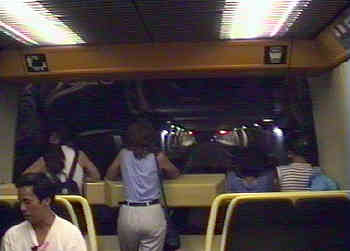
Trains which are designed for use at GoA levels 3 and 4 do not need 'cab' areas for the driver at the front of the train so instead passengers can enjoy a panoramic view of where they are going,
such as this view approaching a station on the GoA 4 Copenhagen (Denmark) metro.
When first built only the underground stations featured platform edge doors, however it was subsequently decided that the other stations should be retrofitted with them, instead of using the infrared obstacle warning system which some media reports claimed was sometimes too sensitive. Multiple GoA On The Same SystemsIt is usual for each system to only use one GoA, and of course on new-build systems this will be installed as an integral part of the new railway. In the case of large cities that have several underground / metro / subway lines then whilst the different lines might adopt different GoA solutions, it is still usual for each line to only use one GoA. However especially on historic networks this is not always possible. A reason why two different GoA might be used by the same trains as part of a mixed mode service is that the service is partway through the upgrade process from the legacy colour light signalling system to automated operations. But usually this is only transitional and once complete the entire line will use just the one GoA. The upgrade process of several London Underground lines followed this model. When an existing service is also receiving new trains it sometimes happens that there is also a transitional phase when the different trains follow different GoA. An example of this was Paris Metro Line 1 whilst the GoA 4 UTO trains were being introduced on a service that already used GoA 2. However, sometimes it is not possible to fully automate a service, which means that train operations will always include a mix of several different GoA. As is explained further down this page, this will be the situation on the sub-surface Underground lines in London which mostly date from the days of steam trains and for historic reasons include much interworking with other trains. An example of two different GoA being used by the same transport can be found in San Francisco where the Muni Metro Light Rail streetcars use in GoA 0 when travelling in street mode and GoA 2 when travelling through the Market Street Subway and Twin Peaks Tunnel. Automation was introduced because it was felt that it would offer better control of the five high frequency streetcar services when travelling on shared fully signalled trackage below ground. |
|||
 |
 |
||
| Muni Metro Breda streetcar on route J travelling in street mode calls at the Church and Clipper stop. |
Muni Metro Breda streetcar in ATO mode at the subterranean Church station. Image & license: p_x_g / Wikipedia encyclopædia. CC-BY-2.0 https://commons.wikimedia.org/wiki/File:Church_MUNI.jpg |
||
|
Converting Muni Metro tunnel services to automated train operations was a high profile prestigious multi-million US$ project. The aim was to increase capacity from 24 to 48 services an hour. Unfortunately things did not go well and at times there were "meltdowns" (service collapses) when it became quicker to walk! The first link below leads to a page at the website of an organisation for regular Muni Metro passengers (especially commuters) called Rescue Muni which discusses some of the alleged reasons why things went so badly wrong, these include:
http://www.rescuemuni.org/meltdown/meltdown.html It is important that transport operators, planners, politicians and the travelling public do not automatically assume that because something is expensive and works well elsewhere that it alone will also be "the solution they have been looking for" for the transports in their cities. Money alone does not make things good! (It is possible that the financial institutions which lend the funds that finance the projects will disagree with this comment). Hi-tech solutions may be sexy but that is no guarantee of success! What happened in San Francisco was very painful for everyone who was involved but it offers valuable lessons from which other cities can profit. Automation Weak Links1) Jerky Train Journeys Human train drivers usually offer a smoother ride for the passengers! This is because when, during the journey, automated trains maintain progress / adherence to the timetable and speed limits by switching between acceleration and coasting they tend to do so by applying short bursts of full power acceleration interspersed with coasting - or even braking, if the speed limit might be about to be breached. This "kangaroo hopping" style of driving can be very jerky. By way of contrast, human train drivers will usually use partial power (or braking) ratios such as a third, a half etc., as these make for smoother journeys and is also better (kinder) on the train's mechanical components. 2) Loss Of Communications = All Stop! Nowadays automated railways (especially those which use 'moving block' signalling) tend to work on the basis of the trains being in constant two-way communication with the central computers, so that they always know the exact locations of the trains. Depending on the sophistication of the automation technology the central computers might also be able to use their awareness of where all the trains are to ensure that the desired service frequency is being maintained. On fully unstaffed GoA 4 systems this headway control is managed by the central computers telling late running trains to reduce the station stop dwell times and travel faster when between stations (albeit always remaining within the speed limit) whilst trains which are little early can be told to travel at slightly lower speeds and to spend a little longer when at stations. On GoA 2 / GoA 3 systems the headway is controlled through train speed and advancing or delaying the 'time to depart' signal that is given to the member of staff who controls door closing and initiates station departure. Some really sophisticated systems even adjust the information about the next stage of the journey in real-time. For instance if the station stop duration was longer than expected the train will then be told to travel a little faster so as to help maintain the desired headway. Less sophisticated systems only make such corrections at the start of the next station stop. For most of the time this is all well and good, but if the two-way communications signal is lost so that the central computers no longer know where the trains are and the computers on the trains are not receiving coded information telling them what to do then the system tends to fall over - or in other words, everything comes to a grinding halt - as this is the only realistic way of ensuring absolute safety. Where there are railway staff on the trains it is often possible for them to take control of the train and in conjunction with the staff at the control centre override the 'no code / automatic stop'. For safety reasons (to reduce the risk of colliding with a train in front - especially when in tunnels or at night) trains which are travelling in this emergency mode are normally restricted to a very slow speed. Typically this will be something like 10mph or 15km/h. If the fault is 'just' that one train has lost the ability to send and receive the communication signals then it is usually possible for the train to be driven at this very slow speed to somewhere where it can be taken out of service and stop blocking the rest of the route. But, at that very slow speed it is inevitable that all other trains behind it (plus the passengers!) will experience very significant delays. 3) Low Adhesion - Spinning And Sliding On Slippery Rails (This issue applies to ALL steel wheeled railways - high speed, regional, urban metro etc., but automated railways suffer more severely) A known issue with steel-wheel railways is that the wheel / rail interface can be impaired when the tracks are wet or slippery. This is rarely an issue when operating in tunnels but it can become a serious impediment where trains travel above ground / in open air. When accelerating, especially from rest (eg: to depart from a station) low adhesion manifests as the powered wheels rotating more quickly than the train is travelling, whilst when braking (eg: to stop at a station) low adhesion manifests as braked wheels either rotating more slowly than the train is travelling or in a 'worst case' situation not rotating at all. Wheels rotating at different speeds than the train is travelling is wheel spin whilst when the wheels stop rotating altogether - so that the train is sliding along the track - is wheel slide. Especially wheel slide can be dangerous, as it implies that the train could be careering along the track out of control and unable to stop. Whilst this does happen from time to time, accidents caused by it are rare - although perhaps more by good fortune / sheer good luck than intelligent design. To help mitigate the problems caused by low adhesion many trains are equipped with "wheel slide protection" technologies and the ability to spread some sand on the rails immediately in front of the direction of travel. Using sand is a well-proven way of helping the wheels to grip the rails. In addition, if the weather forecast suggests that wet weather is likely transport operators can vary the timetable and require that trains are driven in ways that reduce the likelihood of slipping and sliding. This usually means slower braking, which equates to needing longer distances and taking more time to stop the train, these both being luxuries that on high capacity urban railways which feature very frequent services and closely spaced stations seriously degrade the service and reduce the number of trains that can be operated. Ultimately however it is the duty of the train driver to minimise the risks. By looking at the weather conditions and rail track surface, human train drivers are more likely to know when wheel slip / spin are likely and be able to drive the trains in ways which compensate for these conditions. Whilst this may include their initiating braking sooner and at a less powerful rate, as per the paragraph above, an experienced human train driver will be able to 'feel' how the train is braking and adjust the braking rate in real-time. By way of contrast, computers are less clever, less capable and less able to 'feel' how the train is slowing and react accordingly. Sometimes the only way around this is for all trains to be run in minimum braking mode, and to run fewer trains with extended journey times - which potentially can be significantly longer, if long sections of railway are above ground. An added hazard faced by automated railways, especially those which use moving block signalling and base their locational awareness upon wheel revolutions, is that if they experience wheel slip or wheel spin their onboard computers detect this as an error and behave in the same way as when trains have lost their ability to communicate with the central train operations computer. Since the error is only on that specific train it is possible to recover the situation and resynchronise with the central computers by travelling at the usual very slow default safety speed until a location that has been designated as being suitable for this process has been reached. However, even if the delay whilst all this occurs is 'only' ten minutes it still messes up the service, causing significant inconvenience to the passengers.
An Exploration Of Some Automated Urban Railways |
|||
London's First Driverless Railway Opened In 1927!Whilst this page primarily looks at passenger railways one noteworthy non-passenger railway which used unstaffed trains that merits a mention is London's Post Office Railway. |
|||
 |
 |
||
| A "mail rail" train on London's Post Office Railway. The through tracks are just visible to the left of the train. Image & license: Richard Pope / Wikipedia encyclopædia. CC BY-SA 2.0 http://commons.wikimedia.org/wiki/File:London_Post_Office_Railway.jpg |
Side elevation of a Royal Mail Mail Rail Train.
Image & license: Ross Holdway / Wikipedia encyclopædia. Public Domain http://commons.wikimedia.org/wiki/ File:BLW_Royal_Mail_Mail_Rail_Train.jpg |
||
|
The trains were electrically powered using a 3rd rail which was energised at 440v dc between stations and at 150v dc within the stations. Although they were driverless their routing was controlled using lever frames
located at the stations, with express trains being directed to through tracks around stopping services at intermediate stations.
|
|||
The First (Passenger) Automation - New York CityWhat is believed to have been the passenger-carrying automated urban railway was the IRT Grand Central-Times Square Shuttle on the New York City, USA, Subway. The project for an automated train actually began in 1959, and by the spring of 1960 early automation trials were underway on a remote section of track which would not interfere with other passenger services, this being between New Utrecht Ave and 18th Ave. Testing continued for many months, during which time various changes and tweaks were made to refine the technology. In March 1961 work began to convert track 4 of the Times Square - Grand Central Shuttle to be suitable for automated operation, and later in the year the train began running without passengers. Passenger services began in January 1962. Agreement was reached with the unions for a motorman to ride in the train at all times - whilst the unions may have been concerned about the future loss of employment for its members with present-day eyes it could also be seen as having been more of a PR gesture to reassure passengers than a technical need. Services continued until April 1964 when a fire in 42nd Street station ended up significantly damaging the automated train and buckling the steel beams holding up the station roof, forcing the closure of both the station and the street above - in case it collapsed into the station. The fire's cause was not related with the automated shuttle train and with the wayside / relay equipment (a short distance away from the train) having been completely unaffected it was entirely feasible that once structural repairs had been effected and the rolling stock also repaired or replaced automated operations could have resumed. However, by 1964 the management in charge of the New York Subway had changed and the new people had no interest in automation, so when the services restarted all trains were manually driven again. The above information represents a brief precis of a much more detailed article on the nycsubway.org website. The full page can be reached at this link...
http://www.nycsubway.org/lines/irtshuttle.html Since then automation has been off the agenda for the Subway, although (as is seen below) New York's AirTrain JFK service is an automated rail service. London - First With Multiple Automatically-Driven & Human-Driven TrainsAfter initial safety trials proved successful Londons' first automatically driven passenger train ran on the District Line in 1963. These initial trials involved just one specially modified train travelling eastbound between two stations (Stamford Brook and Ravenscourt Park) as part of much longer District Line journeys. Although the train drove itself the human train driver always remained in the cab to oversee events. All other eastbound trains travelling between these two stations continued to operate in normal 'human driven' mode. With further trials between these two stations continuing to prove successful, in 1964 full scale trials of automatically operated trains began on the Hainault - Woodford section of the Central Line, which at that time was operated as a small branch-line shuttle service. Initially a dedicated fleet of four trains was involved, later all the new trains destined for what was to become the first full automated line (and is known as the Victoria Line) were tested here too. Because the shuttle service operated over tracks used by other trains so these trials effectively featured shared operation of automated and human driven trains. The latter included Underground trains on both the Epping route as well as (between Woodford and Grange Hill) on peak-hour 'extra' workings travelling to & from Hainault depôt (which is located between Hainault and Grange Hill stations). These trials began at a time when many of the surface stations still had goods yards and the mainline railway operator (British Railways) still ran goods / freight trains to Epping and Newbury Park via Woodford. In addition in those days British Railways also still operated some passenger trains on the Epping route (both normal service and Sunday excursion - typically to south coast seaside resorts), so these trains too would have travelled on at least part of the route that was being used by the automated trains. By 1964 BR was well underway in its process of replacing steam locomotives with diesel engines (for goods and excursion trains) and diesel multiple units for regular scheduled passenger trains. So whilst unlikely it is not impossible that some of the BR trains which travelled on the same section of railway as the automated underground trains were hauled by steam locomotives! British Railways operated trains here because these sections of railway date from the steam train era (built between the 1860's and 1904) and even after the introduction of London Transport's electric tube trains a few mainline
railway passenger and goods (freight) trains were still run. The last goods trains ran in 1966 and the last diesel passenger trains (on the Epping service) in 1970. The mixing of self-driving automated and manually (human) driven trains was possible because the automated system overlaid and followed the existing traditional style signalling 'block' system whereby the track is split into predetermined fixed size sections (or 'blocks') with semaphore or colour light signals located along the line telling a train driver whether it is safe to enter the next block section. With this system the signalling system is itself blind to the type of train using that section of track - more modern signalling systems use moving block systems where the trains and signalling systems interact with each other so that there is a moving 'safety zone' into which following trains must not enter which always travels with the train (right behind it). Advantages of the moving block system include that by using trains with predictable operating characteristics they are able to travel at closer intervals whilst still maintaining absolute safety, which translates into more trains being operated; the disadvantages include that the trains need to be able to interact with the signalling system - which means that only trains which carry the required communications equipment can be permitted to use the section of railway.
|
|||
 |
 |
||
| One of the shuttle trains used on the Hainault - Woodford route to test the automated passenger train technology.
Automated operations started in 1964, which was whilst British Rail mainline goods (freight) and passenger trains were still travelling along the same tracks, although after steam locomotives had been replaced by diesel traction. |
One of the then new trains destined for the Victoria Line in passenger service on the Hainault - Woodford route, seen alongside a manually driven train as used (at that time) on the rest of the Central Line.
These trains started using this line in 1968, which was after goods (freight) trains had been withdrawn but whilst the British Rail diesel passenger trains were still in operation. |
||
FACT - Fully Automatic Control of TrainsIn the late 1970's one of the shuttle trains was converted for trials of NOPO (no person operation), although on those days it was known as NOMO (no man operation). These trials were carried out between Hainault and Woodford when the railway was closed to passenger services. When operating in fully unstaffed mode a blue light on the left of the destination blind box was illuminated. This project was called FACT - Fully Automatic Control of Trains. The FACT project is understood to have concluded in 1978, due to lack of finance to progress it further. |
|||
 |
 |
||
| Extra signage at the platform end reminds railway staff that automated trains are being used on this section of railway. | One of the original Victoria Line trains arrives at Kings Cross Station, London. As of June 2011 these trains were replaced with a new fleet of trains. |
||
 |
Close-up view of the front left of a first generation Victoria line train (the 1967 Tube stock) showing the receiver unit which detected the codes (from the running rail) used by automatic train operation system.
The rail nearest the camera is the live power rail and also seen here is a pick-up shoe which collects the power from that rail. The rail is rusty because this train was on a little-used depôt track. |
||
|
With safe operation of all the trains having been proven the new Victoria Line was able to open in September 1968 as London's first fully automated underground line. Despite plans for further automation nothing more actually happened (on London's Underground) until the 1990's, when the entire Central Line was equipped with new trains and converted to fully automated operation - albeit with a driver still in the cab controlling the passenger doors. (not illustrated). However whilst London rested on its laurels (took a siesta?) automation found favour in other countries and now the list includes cities such as Paris, Berlin, Lille, Lyon, Vancouver, Barcelona, Manilla, Hong Kong, Kuala Lumpur, San Francisco, Montréal, plus many, many more. Two Trains - Same Station Platform!A design feature of the Victoria Line's signalling was that at busy times, when trains were operating at a high frequency, a slowly moving train could be entering a station platform whilst the rear of an accelerating departing train was still also in the station. This was possible because the signalling was designed to permit slow moving trains to be close together in this way. However, the sight of two closely spaced moving trains partially at the same station platform upset passengers so much that the signalling system was later modified to prevent this from happening. Automation 'In Place' UpgradeThe automated train control system used on the Victoria Line was developed 'in house' by London Transport and gave over 40 years of almost entirely trouble-free and safe service. It was finally deactivated in July 2011, after the introduction of a fleet of new trains which use wireless communication technology and a more sophisticated computerised 'moving block' signalling system. During the period when the new trains were being introduced into service (ie: whilst some trains from each fleet were being used) the new trains used a hybrid system which allowed them to operate under the protection of the existing signalling. This was the first time that an automated passenger railway has been upgraded with a newer automation technology in this way. (The Taipei, Taiwan upgrade and conversion was different - it was as part of a line extension with the existing rolling stock being adapted for the new train control system - not replaced; as detailed below). In addition to the new train control systems, the completion of the upgrade process has enabled the new trains to start using their regenerative braking which recycles braking energy into the track for other trains to use. The newer trains have a maximum service speed of 50mph (80km/h), which now that they have exclusive use of the line they can reach and maintain without constantly catching up the slower (47mph / 74km/h), older trains in front. |
|||
 |
 |
||
| Two of the second generation Victoria Line trains (the 2009 tube stock) seen at the only Victoria Line location which is above ground (Northumberland Park Depot).
Image & license: Steve Mcsherry / Wikipedia encyclopædia. Public domain. http://commons.wikimedia.org/wiki/File%3A09NPKDT.jpg |
The new trains include wheelchair spaces (as seen here) and their introduction saw most Victoria Line stations being equipped with raised platform sections which facilitate 'easy access / level entry' to the same part of the train. | ||
More London AutomationsMore recently two other London Underground lines have been resignalled for automated train control. The Jubilee and Northern Lines both use modern trains which were built with this conversion in mind. But because of the way privatisation fragmented train operations and decision making, rather than using the same automation system that had just been installed on the Victoria Line they use a rival technology. This means that the London Underground network comprises a hotch-potch of incompatible technologies. In addition, since not all maintenance trains have been fitted with the necessary equipment to interface with all the different technologies the situation has arisen whereby nowadays the maintenance fleet can only travel along some lines at night - when passenger services have finished. Whereas the 1960's automation trials on the District and Central Lines saw automation being overlaid on top of a traditional signalling system which facilitated shared use of the same tracks by both automatically and human-driven trains, the Jubilee and Northern Line conversions have been made on the basis of tracks which are used exclusively by compatible automated trains. One knock-on effect of this was that the (2011) conversion of the Jubilee Line required the withdrawal of the remaining (human driven) Metropolitan Line trains which travelled over Jubilee Line tracks on the four track route in north London. In addition, it ceased to be possible for trains in passenger service to use the tracks of the 'other' line at times of disruption or planned maintenance works. Instead services have to be withdrawn and passengers inconvenienced. Converting the Jubilee and Northern lines to full automation was accomplished by splitting the line into segments and converting them one segment at a time. At segment boundary stations the trains switched between ATO and manual driving. Note that the splitting was 'virtual', it only applied with respect of signalling - the trains continued to travel along the entire line (as before) and to passengers the process was seamless. |
|||
 |
 |
||
The process of enabling the automated train operations included covering the existing colour light signals so as to ensure
that the train drivers did not see what was now redundant equipment. At a later date the signals were completely removed. These views show a southbound station departure signal whilst still in use at Burnt Oak on the Northern Line (left) and covered over by a plastic bag a few weeks later, with the ATO now controlling train operations.(right). London Is UnusualWhereas most urban transport systems were built as such from the outset and typically have exclusive use of their tracks, some of the older parts of the London system date from times when there were many private companies, some of which shared operations with other railway companies on the same sections of track. Some of these shared operations still exist and the needs of the other railway operators have to be taken in to account when resignalling the lines and installing modern-day train control technologies. Another issue is that on some of these routes the Underground trains are the 'guests' so London Underground Ltd does not control the signalling. Historical Return: More Mixed Operations In London With
|
|||
 |
 |
||
| Although designed for automation London's Docklands Light Railway trains include the facility for the onboard member of staff to drive them manually. To prevent passenger abuse the controls are normally kept in a locked compartment and require special equipment to activate. | The automation system used on the DLR sees trains communicating with the railway's control centre via a continuous 'leaky cable' located midway between the tracks. Loss of communications results in trains coming to a halt. | ||
 |
 |
||
| The view out the back of a DLR train at Canary Wharf Station. Note the how closely the train behind has drawn up. The DLR uses a computerised "moving block" signalling where the slower a train is travelling the smaller the 'safety zone' between it and the train in front needs to be. This is because lower speeds require shorter braking distances. |
Next to every doorway DLR trains include a control panel which is used by the PSA as described below. Also seen in the photograph is a button which is used by passengers to open the doors. The button is surrounded by a clear plastic ring which illuminates at station stops to advise passengers that it is active. |
||
A DLR PSA can close the doors from any set of doors along the train. The image (above - right) shows one of their control panels - these are located next to every passenger doorway. The lights illuminate at every position throughout the train, although only the PSA can make the buttons work:-
As previously stated, not everyone likes unstaffed trains - some passengers suggest that they make them feel distinctly uneasy just in case there is a failure. This fear of things that drive themselves - though understandable - is irrational because although very rare when rail accidents do occur the majority of them can be attributed to human error - often by the signalmen or train driver (passing a red signal, when it is not safe to do so - SPAD [signal passed at danger] - being a known issue) and it is the fitting of automated safety systems that override human errors that these incidents can usually be prevented. The real danger is to be found on the roads where there are so many accidents that the media generally only reports them when they involve either major carnage or multiple deaths. Also Planned For Automation In LondonAlso to be automated in London will be the core sections of the Thameslink and Crossrail (Elizabeth Line) services. Both routes involve trains which are part of the mainline (national) railway network that travel through central London and when fully operational these will represent the first time that such trains have been automated. Thameslink trains travel north-south on routes which are over 100 years old. The central London core of Crossrail's Elizabeth Line is still under construction, when fully open (in 2019) its trains will travel east - west, with interchange between both routes at Farringdon station. In both cases only part of the routes served are being automated. For the rest of the time the trains will follow legacy style signalling systems. Special emphasis is being placed on ensuring that the transitions between signalling systems at boundary stations is seamless. The Thameslink plan is as part of a wider scheme in which there will be a new fleet of trains and a partial resignalling using the new ECTS system between Elephant & Castle and Kentish Town stations. The aim is that a combination of automatic train operation and cab signalling will facilitate running up to 24 trains an hour (per direction) in the peak hours through the core Central London segment between Blackfriars and St Pancras stations. For the present-day national railway system this is seen as being a high frequency. ECTS (European Train Control System) is the train-control element of the European Rail Traffic Management System (ERTMS). It works by informing the train of the maximum distance that it can travel, the speed profile of the track ahead and other track information about the route the train will be travelling. The driver can then drive the train, but if the distance or speed limit is exceeded, or is in danger of being exceeded, the ETCS on-board equipment will intervene to control the train, bringing it to stand, if necessary. In the case of Thameslink an ATO system is being overlaid on the ECTS system, so when in Central London the train driver's duties will primarily be to close train doors and initiate station departure. With trials in autumn 2015 using a Network Rail test train having proven satisfactory (conducted at a time when the line was closed to all other trains) the next stage is to trial the new trains, some of which have now arrived in the UK. Links to more information: |
|||
 |
 |
||
| A test train (Class 313 121) at St Pancras Thameslink station during successful ECTS trials in autumn 2015. This train is also used at a test location near Walton-at-Stone to ensure the correct functionality and interoperability of different suppliers ETCS equipment. Image: Network Rail |
The first of the new Thameslink trains 700110 at London Blackfriars station during the pre-service testing period.
Image & license: Alex Nevin-Tylee / Wikipedia encyclopædia. CC BY-SA 4.0 http://commons.wikimedia.org/wiki/ File:700110_-_London_Blackfriars_3T13.JPG |
||
|
On Crossrail's Elizabeth Line the mostly new build tunnels from close to Paddington Station to a location between Liverpool Street and Stratford stations plus a branch to Abbey Wood via the Docklands financial district is being equipped with radio Communications-Based Train Control (CBTC) moving block signalling. Here trains will operate in Automatic Train Operation (ATO) mode with Automatic Train Protection (ATP). West of Paddington station Crossrail trains will travel on tracks which are going to be equipped with the European Train Control System (ETCS) Level 2. To the east of London the route to Shenfield uses the legacy Train Protection Warning System (TPWS). Although the branch to Abbey Wood includes some pre-existing sections of railway the entire route is being dedicated to Crossrail trains and is receiving the same CBTC signalling as the core Central London subterranean route. The aim is to operate 24 trains an hour (per direction) in the peak hours (through the central core) and if required be able to increase train frequencies to 30 trains an hour. In many ways the newly built deep level underground section of railway between the western tunnel portal - Central London - Abbey Wood / eastern tunnel portal can be seen as a very high capacity urban metro. In part this is because it is vested in
the London local government controlled Transport For London rather than as part of the national railway network. However once on the surface the trains will be sharing tracks used by other trains - both passenger and freight - and there is
a concern that in trying to afford priority to Crossrail trains changes are planned to track layouts which will negatively impact on the other services - and even possibly result in freight being forced off trains and on to roads. Future Automation Plans For LondonWhereas at present all automation on the London Underground has been as GoA 2, it is planned that the next generation of tube trains which will be introduced in the 2020's will be designed for the same automation grade as the DLR, ie: GoA 3, although it is possible that the very short Waterloo & City Line might even be converted to GoA 4. That is, if human politics permits - ie: agreements with trade unions and acceptance of UTO by the passengers. GlasgowIn March 2016 it was announced that the Glasgow Subway is to be converted to becomes the first British UTO (unattended train operations) urban passenger transport system*. There will be a new fleet of fully walk-through trains which have glass ends, so that passengers can enjoy forward views of their journeys. In addition, all stations will be fitted with platform screen doors. To preserve as much space and openness within the stations as possible while still maintaining passenger safety and security these will be of the 'half-height' variety. *Airport shuttles serving just a couple of stations excepted. Automation OverseasIn February 1981 the Japanese opened the first urban automated guideway transit (AGT) of the present era. The Kobe Port Island Line (commonly known as Port Liner) was built to link and open up for development the artificial island of Port Island with Sannomiya Station, Kobe's main transit hub. The line also serves the new Kobe Airport, which was built on an artificial island near Port Island. |
|||
 |
 |
||
| Kobe New Transit 8000 trainset.
Image & license: Peee / Wikipedia encyclopædia. CC BY-SA 3.0 http://commons.wikimedia.org/wiki/File:Portliner_8000_01.jpg |
In Kobe the line ends at JR West Sannomiya station, where passengers can interchange with other transport services. This image also shows the short wheelbase nature of these trains.
Image & license: Tennen-Gas / Wikipedia encyclopædia. CC BY-SA 3.0 http://commons.wikimedia.org/wiki/ File:Sannomiya_Station_001.JPG |
||
Tokyo's first AGT system is the New Transit Yurikamone, which when it opened in 1995 was known as the Tokyo Waterfront New Transit Waterfront Line. This line serves the artificial island of Odaiba which has become a popular entertainment and leisure destination. Despite charging premium fares and there being cheaper (subterranean) alternatives the line is popular because being elevated it offers passengers excellent skyline views. Carrying over 100,000 passengers per day it makes a net profit and will fully pay off its construction cost loans more quickly than the originally anticipated 20 year period. The line is 14.7km (little over 9 miles) in length and serves 16 stations. |
|||
 |
 |
||
| The New Transit Yurikamone, Tokyo, Japan.
Image & license: LERK / Wikipedia encyclopædia. CC BY-SA 3.0 http://commons.wikimedia.org/wiki/File:Yurikamome-7280.jpg |
Being fully automated means that there is no need for a cab for a human driver, so these trains can offer passengers grandstand front window views of where they are going.
Image & license: Tennen-Gas / Wikipedia encyclopædia. CC BY-SA 3.0 http://commons.wikimedia.org/wiki/File:Yurikamome_001.JPG |
||
By way of a contrast, the Horishima Astram Line The clickable larger images will allow for a |

The Horishima Astram Line. Image & license: LERK / Wikipedia encyclopædia. CC BY-SA 3.0 commons.wikimedia.org/wiki/File: Astram_line_6122_at_Omachi_station.jpg |
||

Image & license: Hisagi / Wikipedia encyclopædia. CC BY-SA 3.0 http://commons.wikimedia.org/wiki/File:Astram_Line_1000_02.png |

Image & license: Hisagi / Wikipedia encyclopædia. CC BY-SA 3.0 http://commons.wikimedia.org/wiki/File:Astram_Line_1000_03.png |
||
| Inside the short wheelbase trains on the Horishima Astram Line. These views show the layout of the seating, how the cab wall is partially glazed so that some passengers can still benefit
from a forward view of where the train is going and how despite their short length the carriages have been designed to allow passengers to walk through from one to the next. |
|||

Image & license: PekePON / Wikipedia encyclopædia. CC BY-SA 3.0 http://commons.wikimedia.org/wiki/File:Toneri-koen_Station.jpg. |

Image & license: PekePON / Wikipedia encyclopædia. CC BY-SA 3.0 http://commons.wikimedia.org/wiki/File:Toneri-koen_Station_gate.jpg. |
||
| Street level and ticket sales area views of Toneri-koen Station on the Tokyo Nippori-Toneri Liner. Note the tactile flooring which passes through one of the ticket gates. Some people may baulk at the elevated nature (over a roadway median) of the line, however in a crowded cityscape this makes excellent sense; it is safer than having the transport at grade and with overall system construction costs in mind being elevated represents a much more cost effective solution than locating the system below ground. In 1983 the French city of Lille opened the first métro system with fully unstaffed trains. |
|||
 |
 |
||
These trains use the 'VAL' system which nowadays exists in several cities including Paris, Toulouse, Rennes (France), Turin (Italy), Chicago (USA) & Uijeongbu / suburban Seoul (Korea). The name 'VAL' was originally used because it represented the route of the first line - Villeneuve d'Ascq à Lille (ie: Villeneuve d'Ascq to Lille) - but now it officially stands for véhicule automatique léger, or automated light(weight) vehicle. The term 'lightweight' refers to the fact that at just 26 metres in length (two linked cars), 2 metres in width and with a passenger capacity of 152 per twin-unit train the (original) VAL trains are smaller in size and mass than traditional trains. They partially make up for their low passenger capacity however by being able to operate at headways as close as 60 seconds. The advantages of using 'lightweight' trains such as these is that it reduces the cost of building the system. Shorter trains require shorter (cheaper to construct) stations whilst lighter-weight railcars require physical infrastructure which is of a lower mass and therefore also less expensive to construct. Instead of steel wheels VAL trains use rubber tyres, so it could be said that this system follows the French passion for rubber-tyred métros. In 2006 a successor to the VAL system was announced. The NeoVal will use a single central rail for guidance and will be able to operate without any electrical supply between the stations (no third rail or overhead), making the cost of infrastructure much lower. Instead trains will use onboard electric storage technologies, with this being recharged whilst calling at stations. |
|||
 |
 |
||
| In Lille the station platforms are 52m long - this being long enough for single or double unit trains. However, as this view out of a train's front window shows, some subterranean station platforms include unused extension sections. The idea is to facilitate easy conversion to longer trains without the massive expense and disruption of extending the stations whilst in passenger service. | A feature of Lille's métro (and subsequent VAL systems) is that the stations have extra doors on the platform edges - these are supposed to increase safety by preventing people from falling (or being pushed / jumping) in front of approaching trains.
Platform edge (or screen) doors are looked at in greater detail on the Stops and Stations page. |
||
 |
 |
||
| Most of the line is either elevated or below ground; for safety reasons at grade (ie: surface) sections need to be well fenced. | Internal view of one of the original Lille VAL mini-métro trains. | ||
 |
 |
||
| As the Lille system expanded it purchased additional trains which were of newer design. This Line 2 image shows one of each train type. Left: the newer VAL 208 Right: the original VAL 206. Image & license: Jérémy-Günther-Heinz Jähnick / Wikipedia encyclopædia. CC BY-SA 3.0 https://commons.wikimedia.org/wiki/File:Ligne_2_du_m%C3%A9tro _de_Lille_M%C3%A9tropole_-_Garage-atelier_du_Grand_But_(08).JPG. |
A revised internal layout. Only some carriages feature this style of seating which also creates space for 'personal wheeled transports' - the rest have proper seats on both sides. | ||
 |
 |
||
| This 2010 view of a Lille VAL 208 train clearly demonstrates the rubber-tyred nature of the VAL system and that it features single axles flanked fore and aft by sideways facing guidance wheels. | Inside a Paris Orly Airport (Orlyval) VAL train..
Image & license: / Wikipedia encyclopædia. CC-BY-SA-2.5 https://commons.wikimedia.org/wiki/File:Orlyval_-_Interieur_VAL_206_01.jpg. |
||
 |
 |
||
| VAL 208 bogie as seen in Rennes, France.
Image & license: Leotard / Wikipedia encyclopædia. CC BY-SA 3.0 https://commons.wikimedia.org/wiki/File:Bogie_VAL_208.jpg. |
Toulouse VAL Viaduc de la ligne A a Balma-Gramont
Image & license: Louloutte31 / Wikipedia encyclopædia. CC BY-SA 3.0 http://commons.wikimedia.org/wiki/Image:MetroA.jpg. |
||
|
The 11.2km (7.0 miles) long VAL system in Uijeongbu, Seoul Capital Area, (South) Korea is known as the U Line. The "U" stands for the name of the city - Uijeongbu. |
|||
 |
 |
||
| Uijeongbu U Line VAL208 railcar
Image & license: Minseong Kim / Wikipedia encyclopædia. CC BY-SA 3.0 http://commons.wikimedia.org/wiki/File:Uijeongbu_ULine_VAL208.jpg. |
The end of the line... designed to facilitate a planned extension
Image & license: Korail2012 / Wikipedia encyclopædia. CC BY-SA 3.0 https://commons.wikimedia.org/wiki/File: %EB%B0%9C%EA%B3%A1%EC%97%AD_%EC%A 4%91%EB%8B%A8%EC%A0%90.JPG. |
||
|
So far the Italian city of Turin (Torino) only has one VAL line, but at least one more line is expected to be built. |
|||
 |
 |
||
| In the stations the trains travel through a glass tunnel, reducing tyre noise and making it easier to air-condition the platforms. This view of XVIII Dicembre station also shows
some commercial advertising of what some people would see as a somewhat inappropriate type for a public transport system.
Image & license: Luigi Capozzi / Wikipedia encyclopædia. CC BY-SA 3.0 commons.wikimedia.org/wiki/ File:Metro_Turin_Italy_XVIII_Dicembre_station.JPG. |
Although the stations are stylishly designed with marble walls and muted lighting it seems that there is something about the system which the transport operators are very much ashamed (or very fearful?) as the station security staff become very upset if anyone tries to take photographs (of course hand-held and without flash) - even at around midnight, when the system is relatively quiet. This explains why there are so few photographs of the visually attractive stations. | ||
VAL Line Converted To A Different Automation Technology!One former VAL system has been converted to a different (rival) automation system. This is in Taipei, Taiwan. A very simplified history of this system is that in 1988 Matra won the design and build contract for an elevated VAL medium capacity metro system known variously as the Taipei Metro Muzha Line, the MRT and the Taipei Rapid Transit System. The plan was that it would start carrying passengers in 1991. However the construction period of the core infrastructure was very long and protracted, with many delays, fires, other problems, etc., and in 1994 Matra gave up and pulled out of the project. Nevertheless by then construction had progressed far enough that when (in 1996) the metro finally opened it was still able to use VAL automated train technology. After pulling out Matra filed a lawsuit for its losses against the Taipei Department of Rapid Transit Systems (DORTS), which after a protracted 12 year legal battle it won. Always part of the plan was that this metro line would be extended, but with Matra no longer involved a different supplier was required. In 2003 Bombardier was awarded a contract to supply its Innovia 256 trains and CITYFLO 650 moving-block ATC (automatic train control) system on both the planned extension and as a replacement for the fixed-block ATC on the existing line. The project also included converting the existing VAL 256 trains to use the CITYFLO 650 ATC system, so both fleets could be used throughout the entire extended metro line. Shortly after the 2009 opening of the extension, which was known as the Taipei Metro Neihu Line, the older Taipei Metro Muzha Line was renamed the Taipei Metro Wenshan Line. However the combined line is known as the Taipei Metro Wenhu line. |
|||
 |
 |
||
| A view from street level showing an elevated section of the Taipei metro Wenshan-Neihu Line at the HePíng East Rd - FùXìng South Rd junction in Da-an District.
Image & license: Lord Koxinga / Wikipedia encyclopædia. CC-BY-SA-3.0 http://commons.wikimedia.org/wiki/File:2010_07_ 21570_6839_Da%27an_District,_Taipei,_Heping_Road,_Fuxing_Road, _Taipei_Metro_Muzha_Line,_Viaducts,_Composite_bridges,_Taiwan.JPG. |
VAL 256 trains at reversing sidings at Zhongshan Junior High School station, Muzha Line, Taipei MRT. Taiwan.
Image & license: mailer_diablo / Wikipedia encyclopædia. CC BY-SA 3.0 http://commons.wikimedia.org/wiki/Image:VAL-Zhongsan-Reverse.JPG. |
||
 |
 |
||
| VAL 256 Taipei MRT Train No.28 at Taipei MRT Daan Station.
Image & license: Jiahwang / Wikipedia encyclopædia. CC-BY-SA-2.5 http://commons.wikimedia.org/wiki/File:Taipei_MRT_Train_VAL256_No_28.JPG. |
Inside VAL 256 Taipei MRT train.
Image & license: mailer_diablo / Wikipedia encyclopædia. CC BY-SA 3.0 http://commons.wikimedia.org/wiki/File:VAL256-Interior-Center.JPG. |
||
 |
 |
||
| Bombardier Innovia MRT train.
Image & license: merec0 / Wikipedia encyclopædia. CC-BY-2.0 https://commons.wikimedia.org/wiki/File:Taipei_MRT_-Bombardier.jpg. |
Bombardier train about to enter Zhongshan Junior High School Station. Image & license: CCY18999 / Wikipedia encyclopædia. CC BY-SA 3.0 https://commons.wikimedia.org/wiki/File:TRTC_CITYFLO650_IN_Wenhu_Line.jpg. |
||
 |
 |
||
| Front three-quarter view of a Bombardier Innovia MRT train at Muhza depot, showing its livery. Image & license: Shih-Han Lin / Wikipedia encyclopædia. CC BY-SA 2.0 https://commons.wikimedia.org/wiki/File:CITYFLO650_CAR1.jpg. |
Bombardier Innovia train on the left and two Matra VAL256 trains (before modification to the CF650 system) on the right in a trainshed at Muzha Depot, Image & license: Shih-Han Lin / Wikipedia encyclopædia. CC BY-SA 2.0 https://commons.wikimedia.org/wiki/File:CF650_VAL256.jpg. |
||
Another French city with an unstaffed automated métro line is Lyon. This line uses the 'Maggaly' system (Métro automatique à grand gabarit de l'agglomération lyonaise) and the trains feature large panoramic front windows so that passengers can enjoy the view of where they are going. Note that in Lyon only line D is unstaffed / GoA4 and that instead of platform doors the train's doors have sensors to detect clothes, bags or other things that might get trapped, whilst an infra-red system detects obstructions on the platform edge or the track. Although the stations were built to accept trains up to four-carriages in length, the trains are formed of just two carriages. Instead there is a very high frequency service with trains about two minutes apart. |
|||
 |
 |
||
The automated métro line D, Lyon, France.
Several Canadians cities also use automated métros, some of these also use home-grown technology. Originally named ICTS (for Intermediate Capacity Transit System) the Canadian system uses rolling stock known as Canadian Automated Light Rail Transit vehicles (ALRT). This system combines both traditional and several innovative state-of-the-art technologies; for guidance it uses traditional standard gauge steel-wheels-on-steel-rail technology and innovative steerable bogies whilst for propulsion it features innovative Linear Induction Motors (LIM), which is an electromagnetic propulsion system. This was the first major application of LIM technology for urban transport. With steerable bogies the two axles independently follow the track curvature, this significantly reduces flange contact with the rail thereby substantially reducing rail noise as well as bogie & track maintenance requirements plus extends wheel life to almost one million km. |
|||
Linear Induction Motors are straight line' versions of the conventional rotary alternating current electric motor.
|
 A scissors crossover showing the LIM rail between the tracks. |
||
Nowadays the system is known as Advanced Rapid Transit (ART) and a new generation of higher capacity rolling stock has been introduced. The original (UTDC) Mark I cars are 12 m (40 ft) long while the second generation (Bombardier) Mark II cars are 18 m (60 ft) long each and comprise articulated pairs. Several Canadian, American and Asian cities use the ART system. In 1985 Toronto was the first city to open an ART route, and here it acts as an add-on to the pre-existing heavy rail subway and streetcar networks. Although the vehicles are automated all trains carry a driver whose duties include initiating door closure & station departure. Vancouver's system opened in 1986 and here the system acts as a fully automated mini-métro. The 2, 4 or even 6-car trains are unstaffed / driverless and call at station platforms which do not have platform doors. It is called SkyTrain because apart from a short tunnel section in the city centre the initial part of the system was mostly elevated (aka: 'in the sky'). Since opening the network has been extended several times, plus several completely new routes have been built as well, although one of these eschews ART technology. Along with the (electric) trolleybuses and commuter rail the SkyTrain network forms the backbone of Vancouver's urban transport network. |
|||
 |
 |
||
| Fully automated driverless Vancouver SkyTrain on the Expo Line. | Similar trains (with just a few cosmetic differences) are used in Toronto too. | ||
 |
 |
||
| The spectacular SkyTrain 'SkyBridge' over the Fraser River, Vancouver. This cable-stayed bridge is the longest cable-supported transit-only bridge 'anywhere' planetwide. Its total length (including approach spans) is 616 metres (2020 ft.), the main span is 340 metres (1115 ft.) in length and the tower height is 117 metres (384 ft.). | The ART system uses two power rails (positive and negative) as this helps to prevent electrolytic corrosion in underground structures and on the elevated guideway - as well as also providing significant protection against ground faults. | ||
 |
 |
||
| As Vancouver's SkyTrain system expanded it required more rolling stock, and this image shows one of the newer MK11 trains which are of a different design with a higher passenger capacity. Vancouver is
the only city to mix both MK1 and MK11 trains.
Image & license: MStar / Wikipedia encyclopædia. Public Domain. http://commons.wikimedia.org/wiki/File:MKII-Broadway.JPG. |
In Toronto Mk1 trains operate what effectively is a short shuttle service with four intermediate stations which feeds into the subway at Kennedy station. | ||
 |

Image & license: SqueakyMarmot / Wikipedia encyclopædia. CC BY 2.0 commons.wikimedia.org/wiki/File:Bombardier_ART_Mark_II_interior_-c.jpg. |
||
Comparative views inside Vancouver's Mk1 trains left and Mk11 trains right.
Vancouver's SkyTrain system continues to expand although whilst the Canada Line - which opened in August 2009 - also uses automated trains they use different steel wheel technologies. In Detroit single or twin-car Mk1 ART trains travel along an elevated guideway on a 2.9 miles (4.7 km) one-way loop, calling at 13 stations. A complete circuit takes just under 15 minutes and services operate at three to five minute intervals. The DPM (Detroit People Mover) was meant to be a 'downtown distributor' for a planned new rapid transit rail system serving the city, however this was not built. |
|||
 |
 |
||
| Canada Line Skytrain at Vancouver Airport Station.
Image & license: Michaelberry / Wikipedia encyclopædia. CC BY 3.0 commons.wikimedia.org/wiki/File:Canada_Line_Skytrain_Cars-2008-04-22.JPG. |
A DPM (Detroit People Mover) train passing Beaubien and East Larned Streets in Detroit, Michigan. Image & license: Javier Rapoport / Wikipedia encyclopædia. CC BY-SA 2.0 http://commons.wikimedia.org/wiki/ File:Detroit_People_Mover_2.jpg. |
||
|
In New York the ART system is used on the AirTrain JFK service which is an 8.1-mile (approximately 13km) line that connects John F. Kennedy International Airport (JFK) to the city's subway and commuter trains, and airport car parking areas. The AirTrain operates three services, one of which just links the various airport terminals in a clockwise loop whilst the other two serve the terminals in an anti-clockwise loop and then extend towards New York City, splitting enroute to serve Howard Beach-JFK and Jamaica Stations where there are interchange facilities with some New York Subway and Long Island Railroad services (plus many bus lines). Before splitting these services also call at an intermediate station (Federal Circle) to serve the car rental companies, hotel shuttle buses to hotels and the airport's air cargo area. |
|||
Because of its specialist operations servicing an airport the AirTrain is free for to travel within the airport and to / from Federal Circle station. However fares must be paid by passengers either
joining or leaving the AirTrain at Howard Beach-JFK or Jamaica stations.
|

AirTrain JFK - these are double-ended non-articulated vehicles which can operate solo, if desired. Image & license: DearEdward / Wikipedia encyclopædia CC BY-SA 2.0 http://commons.wikimedia.org/wiki/File: JFK_Airtran_(5788298619).jpg. |
||
|
In Malaysia the ART system is used on the Kelana Jaya Line, which is coloured pink on the Kuala Lumpur transit map. The system operates a mix of two and four car trains, with the latter gradually being introduced as more rolling stock becomes available. |
|||
 |
 |
||
| External views of a MKII ART train on the Kelana Jaya Line, Malaysia.
Image & license: Yosri / Wikipedia encyclopædia. CC BY 2.0 http://commons.wikimedia.org/wiki/Image:Yosri042005PuteraLRT.JPG. |
The interior of a Kelana Jaya Line train.
Image & license: Two hundred percent / Wikipedia encyclopædia. CC BY-SA 2.5 http://commons.wikimedia.org/wiki/File: Kelana_Jaya_Line_(train_interior).jpg. |
||
In Beijing, China this system is also used on a dedicated airport service. Known as the Airport Express it is 27km (a little under 17 miles) in length and connects the Beijing Capital International Airport with Dongzhimen in Beijing. In all there are four stops, two at the airport (serving terminal 3 and then terminal 2) and two at interchange stations with the underground railway. Because of its specialist operations servicing an airport and in common with most other dedicated rail-air links the Airport Express charges a special fare that is much higher than the regular fare for the other local transports. This line opened just a few weeks before the August 2008 Beijing Olympic games. |
|||

Image & license: Stephengreaves / Wikipedia encyclopædia. CC BY 3.0 http://commons.wikimedia.org/wiki/Image:Beijing_Airport_Express.jpeg |

Image & license: karismafilms / Wikipedia encyclopædia. CC BY 2.0 http://commons.wikimedia.org/wiki/File:Beijing_Subway_Airport_Express_01.jpg. |
||
The Beijing Airport Express line with Bombardier Mkll cars, which operate as 4-car trains.
Another system which uses non-articulated vehicles is the Korean EverLine. Located in Yongin, Seoul Capital Area, this 18.5km long 15 station service links Everland, South Korea's most popular theme park, with the Bundang Line of the Seoul Metropolitan Subway. |
|||

Image & license: hyolee2 / Wikipedia encyclopædia. CC-BY-SA-3.0 http://commons.wikimedia.org/wiki/File:Everline_102.JPG |

Image & license: Bundang M / Wikipedia encyclopædia. CC-BY-SA-3.0 http://commons.wikimedia.org/wiki/File:Everline_inner.jpg. |
||
External and internal view of the Korean EverLine trains.
Most of South Korea's seven major cities also have urban rapid transit metro systems. Line 4 of the Busan Metro (which is also called the 'Bansong Line') is a rubber-tyred system that uses automated guided transit (AGT) technology. It is 12.7km (7.9miles) in length and has 14 stations, of which 8 are underground, 1 is at ground-level, and 5 are above ground. Meanwhile whilst the Busan - Gimhae Light Rail Transit is also fully automated, it uses conventional standard gauge steel wheel technology. This line links cities of Busan and Gimhae, travelling via Gimhae International Airport, and is 24km in length with 21 stations. |
|||
 |
 |
||
| BTC 4x05 EMU train Busan Metro Line 4.
Image & license: Peremen / Wikipedia encyclopædia. CC BY 3.0 http://commons.wikimedia.org/wiki/File:BTC_4005.jpg. |
Busan - Gimhae Light Rail Transit
Image & license: hyolee2 / Wikipedia encyclopædia. CC BY-SA 3.0 http://commons.wikimedia.org/wiki/File:BGLRT1.JPG. |
||
Cabin Sized Vehicles On An Automated Multi-Train Urban FunicularFaced with severe environmental issues related to motor vehicle exhaust fumes the Italian city of Perugia decided that the only solution lay in restricting car and motorcoach access to parts of the city centre. However they also recognised that another part of the solution lay in improving public transport so that fewer people would want to drive their own cars and that visitors who come by motorcoach should also be happy to leave their vehicles outside of the city centre. Therefore, in addition to increasing car and coach parking capacity on the outskirts of the historic city centre and installing escalators between the parking areas and the city centre, they built a new metro system. Being a small city (population a little below 165,000) on a hilly location they reasoned that they needed a lower capacity system capable of climbing steeper gradients, and wanting to maintain attractiveness by means of a high service frequency they opted to use lower capacity 'cabin' type vehicles which would operate as a funicular railway. Known as the MiniMetro the Perugia system can operate so frequently that waiting time is almost non-existent. 3.2km (2miles) in length the system currently has seven stations, although a second line with two further stations is planned. There are 25 rubber-tyred vehicles which like normal railways can be added or removed from service as required depending on expected passenger numbers. Five metres long each, they are fitted with eight tip-up and one fixed 'special needs' seats and have a maximum capacity of 50 passengers. Other features include an acoustic 'doors closing' alarm and LED display which provides 'next station' and destination updates. The systems' top speed various between 36-43km/h (22-26mph) Services are only cable operated between stations, as at the stations they are automatically detached from the cable and conveyed through the station by an independent conveyor system. Although generally welcomed the MiniMetro has attracted some complaints by people who live close to the route who cite the continuous hum of the cable pulleys as being somewhat noisy. The name MiniMetro is a registered trade mark, so can only be used on systems developed by the Italian company Leitner, who are specialists in automatic aerial ropeways and chairlifts - so it is not surprising that some practices from these transports (such as disengaging from the cable at stations) have been ported over. Along with some other automated 'cabin' transports more photographs of the MiniMetro can be found on the Monorails, Maglevs and 'Cabin' Transports. page. |
|||
 |
 |
||
| An elevated section of line showing how it has been dovetailed to fit between existing residential buildings. In the distance can be seen one of the cutting-edge designed stations.
Image & license: Pava / Wikipedia encyclopædia. Public Domain. http://commons.wikimedia.org/wiki/File:Inforndominimetr%C3%B2.jpg. |
Calling at an underground station.
Image & license: Radapanda / Wikipedia encyclopædia. Public Domain http://commons.wikimedia.org/wiki/ File:90410MiniMetroPG02.JPG. |
||
|
Perugia is not the only conurbation which uses cabin-sized rolling stock for mainstream urban transports - Singapore uses several different commercial systems as local area feeders to the island-wide Mass Rapid Transit railway (MRT) whilst Miami, Florida, USA has a small system which serves the city centre and a few nearby localities. These are looked at in greater detail on the Monorails, Maglevs and 'Cabin' Transports. page. |
|||
 |
 |
||
| The Miami-Dade Metromover in Miami, Florida.
Image & license: Joedamadman / Wikipedia encyclopædia. CC BY-SA 3.0 http://commons.wikimedia.org/wiki/ File:Miami-Dade_Metromover.jpg. |
The Arena/State Plaza Metromover station in downtown Miami. Image & license: Averette / Wikipedia encyclopædia. CC BY-SA 3.0 http://commons.wikimedia.org/wiki/ File:Arena_State_Plaza_Metromover_station.jpg. |
||
Older / Legacy Heavy Rail Systems In EuropeWhilst all the overseas systems seen above were built since the 1980's and as automated systems from the outset, In Paris, France, the first trials with automation took place in 1951. Between 1952 & 1956 trials used a train in passenger service. After multi-train trials in the 1960's the period 1972-1979 saw wholesale conversion of most of the métro system to automatically driven trains. However (at that time) door control and giving the 'starting' signal (after station stops) still remained in the domain of a 'real person'. Note that only some of the Parisian system uses rubber-tyred trains - the rest still uses traditional steel wheel technology! |
|||

Image & license: Pline / Wikipedia encyclopædia. CC BY-SA 3.0 http://commons.wikimedia.org/wiki/File:Metro-Paris-Rame-MP-73-Lign.jpg. |

Image & license: Greenski / Wikipedia encyclopædia. CC BY-SA 3.0 http://commons.wikimedia.org/wiki/Image:MF_77_-_Lecteur_de_grecque.JPG. |
||
| In Paris, the trains collect a radio signal from cables inside a transmitter unit located in an offset position between the tracks.
These images show the transmitter units (see red crosses - left) and the receiver units underneath the front wheel unit (bogie) of a train (right). There are two of these to match the two possible locations for the transmitter units. |
|||
 |
 |
||
In 1998 Paris opened its first fully driverless métro line - line 14 (also known as Météor). This line features stations with platform doors and trains with full walk-through
capability plus large picture windows at the train ends so that passengers can watch where they are going (or, out the back, where they just were!). These views were taken at Bibliothèque François Mitterand station.
With Line 14 being very successful in 2005 it was decided to convert the extremely busy Line 1 to full driverless operation as well. The conversion process included the installation of platform screen doors or gates 1.8m high at every station (they had to be high to prevent people vaulting over them!) and unlike when there are major works on railways in Britain as much as possible was done whilst the system was still operating; ie: with minimal inconvenience to passengers being a part of the process. Where closures were required (eg: for adjusting platform floor heights) stations were tackled one at a time, over a weekend - with the trains still running. The works included station refurbishments and platform alterations to facilitate level access with the train floors. Between November 2011 and December 2012 as the new fleet of driverless trains were introduced the line operated using a mix of unstaffed and staffed trains. After 15th December 2012 sufficient new trains had been introduced to service to permit 100% driverless automated services to become the norm. In July 2013 it was announced that Line 4 will also be converted to fully automated operation. Work will start in 2014 and the project is expected to be completed in 2022.
|
|||
 |
 |
||
| Experimental automatic gates at Gare St-Lazare (line 13) on the Parisian métro system.
Image & license: Pline / Wikipedia encyclopædia. CC BY-SA 3.0 http://commons.wikimedia.org/wiki/File:Ligne-13-Saint-Lazare-2.jpg. |
Platform gates being installed at Bérault (line 1) on the Parisian métro system.
Image & license: Greenski / Wikipedia encyclopædia. CC BY-SA 3.0 http://commons.wikimedia.org/wiki/File: Metro_Paris_-_Ligne_1_-_Berault_-_Installation_facades_de_quai_(20).jpg. |
||
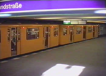
In Germany several cities have hosted trials with automated trains. As part of a Federal Government project the 1960's and 1970's saw trails on the Hamburg U-Bahn. These eventually led to automated passenger services which between October 1982 and January 1985 operated over 10km of railway. Since then however automated operation has been discontinued in Hamburg. Berlin first experimented with automation in 1928, with the system being overlaid upon the existing signal block system near to Krumme Lanke station. The aim was to influence the train over its entire route rather than just at signals. Further trials in 1958/9 with the LZB technique attempted to control train speeds as well, albeit not with enough success to be deemed viable. There was greater success in the 1960's. In 1965 night-time trials commenced between Spichernstraße and Zoological Garden stations on line U9. In 1967 the system was working well enough to hold a press event promoting it. In 1969 the test train was carrying passengers, and by May 1976 the entire Line U9 had been converted to automated operations - albeit initially only during off-peak hours. Full day services began in 1977, and continued for 15 years until 1993, by when age-related deterioration of the system had started to cause issues. 1994 saw a partial reactivation, with the aim of testing automated train reversing at terminals, however these night-time trials did not produce reliable success and with the necessary investments not being seen as being in proportion to the savings achieved so in 1998 the entire project was abandoned. In the 1970's a technology from a rival company was also trialed on a section of elevated U-Bahn that had been closed following the division of the city. This was between Bülowstrasse and Potsdamer Platz stations via the lower level platforms at Gleisdreieck station. The technology was the SelTrac system. With part of the route destined for conversion into the automated magnetic levitation M-Bahn* so the next trials with this technology were switched to Line U4, which is very short and only serves 5 stations. Here trials lasted from 1981 until 1985, when the technology was deemed mature enough to operate trains carrying passengers. Automated passenger services lasted from 1985 until 1993. *The M-Bahn was a 'cabin' transport and is looked at on the Monorails, Maglevs and 'Cabin' Transports page. Between 1996 and 2000 further automation trials were conducted on line U5, between Friedrichsfelde and Biesdorf-Süd stations. Known as the STAR project this used radio technology to communicate with the trains. However with the westward extension of Line U5 from Alexanderplatz being delayed due to lack of finance it was decided that the entire line did not need the benefits which would come from automated operations and when (in 2002) the project was formally ended no further developments were scheduled. The next stage in the long-term plans had been to convert an existing railway to automated operations, and whilst this did not happen in Berlin it was realised elsewhere in Germany. Data sources, both English and German language pages at Wikipedia and these three German language links, via online translation utilities (links open in new windows |
|||
 |
 |
||
| The automation of Berlin U-Bahn Line U4 included the trains being fitted with both audible and visual
'door closing' alarms. Similar alarms were a 'standard fitment' to all East Berlin trains (and trams), although here automation was not on the agenda.
Since unification and the merging of the cities' transport systems back in to one organisation audible & visible door closing alarms have become a standard feature on all of Berlin's trains and trams. |
One of the two-car trains which operated in automated mode on line U4, seen near to Görlitz Bahnhof station on line U1, 26 September 1986. The reason for this train being away from its correct route in unknown.
Image & license: Roehrensee / Wikipedia encyclopædia. CC-BY-3.0 commons.wikimedia.org/wiki/File:19860926a_Automatischer_Zug_Berlin.jpg. |
||
Although developments in Hamburg and Berlin stagnated and even went retrograde, automation was also on the agenda in other German cities. Perhaps the most noteworthy is Nuremberg where a project called RUBIN (Realising an automated U-Bahn In Nürnberg) resulted in the successful realisation of not just Germany's first fully automated / driverless U-Bahn but also the first instance anywhere globally any of a driverless automated system - that was in passenger service - sharing tracks with manually driven trains. This second achievement differed to what has been achieved in London in the 1960's because the London Transport trains still had train drivers - although their main duties were to close the doors at stations, initiate station departure and generally watch over proceedings in case of malfunction or an unexpected obstacle on the track. In Nuremberg line U3 comprises two suburban branches on opposite sides of the city which feed in to line U2 and share its tracks in the city centre. Linking the two branches under the banner of a different line helps passengers plan their journeys. The automated system was implemented as what is called a hot plug-in, which means that it was done without interrupting train services. Line U3 was opened in June 2008. Afterwards the U2 line was automated on a 'train by train' basis as new rolling stock became available, with full automation on the U2 finally being realised in January 2010. German regulations say that trains should not stop inside a tunnel after the emergency alarm has been activated or if any other hazard like a fire is detected, instead they should proceed to the next station, as this will ease rescue operations. Therefore to enhance safety as much as possible and minimise risks to passengers the trains which operate in driverless mode were designed with enhanced safety features including:-
One of the challenges which had to be overcome was the provision of an automated emergency stop system should a passenger or object fall on to the track from a station platform. The usual solution is to fit platform doors, however with some stations already in service it was felt that the severe service disruptions and station closures would have caused too much disruption to passengers. In addition there were concerns about the feasibility of requiring the drivers of Line 2's manually driven trains to stop within the few centimetre tolerance required for the train and platform doors to meet. Initial obstacle detection trails used station roof to platform edge laser light barriers. However the chosen method features a combination of CCTV cameras overlooking the track bed and radio frequency barriers between from under the platform edge to the opposing wall. In the event of something being detected the safety systems will automatically halt approaching trains and alert the control centre, from where a controller can use the CCTV cameras to make a visual inspection and take the appropriate action. Despite being fully automated they still (sometimes) carry a member of staff. This is primarily a customer relations gesture to reassure passengers that all is well, as well as looking out for unruly passengers and offering general travel advice, if need be. |
|||
 |
 |
||
| Driverless DT3 Nuremberg U-Bahn train during the U3 test phase at the Hauptbahnhof (main railway station) underground Station.
Image & license: Tobias Bär / Wikipedia encyclopædia. CC BY-SA 3.0 http://commons.wikimedia.org/wiki/File:DT3_Hauptbahnhof_TB.JPG. |
Nuremberg U-Bahn train at Röthenbach station. This train is on Line U21, which is a variant of the U2 that follows the same route but ends before reaching the airport.
Image & license: Achates / Wikipedia encyclopædia. CC BY-SA 3.0 commons.wikimedia.org/wiki/File:2007-12-27-R%C3%B6thenbach_U_1.jpg. |
||
London - Nuremberg Contrasts. Who Was First With What?The metro automation website cites Nuremberg as being the first city to have automated a previously manually driven underground railway (U-Bahn / metro / subway) and to be the first city to have operated automated and manually driven trains on the same tracks. However, that is not exactly accurate. Back in the 1960's part of the London Transport Central Line was automated, and included both self-driving and manually driven trains travelling (in full public service) over the same tracks. In addition, some of the manually driven trains were diesel powered passenger and freight / goods trains! 30 years later the automated section was upgraded to a newer automation technology and the rest of the Central Line was also upgraded from manual operations to automation. |
|||
Where London's Underground and Nurembergs' U3 differ is that in London the method of automation involves trains which did / still do feature a member of staff who sits in a traditional driver's cab at the front of the train and who closes the train doors prior to initiating station departure. In addition, in London the train drivers still sometimes drive the trains - especially on Sundays - this is necessary because otherwise their license to drive the trains will lapse. By way of contrast Nuremberg's U3 uses fully unstaffed / unattended trains which instead of a train driver's cab have clear glass train ends so that passengers can enjoy forward facing views of the journey. Whilst trains on London's Docklands Light Railway also have clear glass front windows for passengers to enjoy the forward view, they also retain a member of staff who closes the train doors and initiates station departure. |

Glass platform end door designed to deter unauthorised access to the tunnel from the platform. Image & license: Michael Heimerl / Wikipedia encyclopædia. CC BY-SA 3.0 http://commons.wikimedia.org/wiki/File: U-Bahn_Nürnberg_Strecke_Bahnsteigabschlußtüre_OP.jpg. |
||
Direct links to other Passenger Train Variations pages.
 |
|||||||||||||||||||||||||||||||||||||||||||||||||||||
 |
|||||||||||||||||||||||||||||||||||||||||||||||||||||
 |
|||||||||||||||||||||||||||||||||||||||||||||||||||||
 |
|||||||||||||||||||||||||||||||||||||||||||||||||||||
 |
|||||||||||||||||||||||||||||||||||||||||||||||||||||
